Virtual Secure Mode Internals in Hyper-V - Part 1
Introduction to Virtual Processor State
Before getting into Virtual Secure Mode, we first need to understand what is Virtual Processor state.
Virtual Processor state is a structure that’s available for each VTL under a virtual processor and holds a complete guest state of the virtual processor in relation to the VTL.
There are 2 reasons Hyper-V creates and manages the Virtual Processor state structure instead of relying only on VMCS:
- The VP state is used as an efficiency mechanism to share registers between VTLs during a VTL Calls and VTL Returns. There are a defined set of registers that are configured to be shared across VTLs, and other set of registers that are kept private.
A list of shared and private registers: 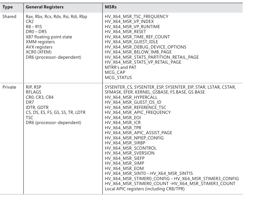
- The second reason, is that the VP state is saving the entire state of the VTL, including certain virtual registers that represent internal Hyper-V mechanism and are not included within the known VMCS strucure. For example, virtual registers that are part of Virtual Secure mode, which we’ll soon see.
To fully understand VSM and it’s relation to Virtual Processor state we’ll reverse the HvCallSetVpRegisters() hypercall.
The following is the function signature of HvCallSetVpRegisters() Rep hypercall.
1
2
3
4
5
6
7
8
9
HV_STATUS
HvCallSetVpRegisters(
   _In_ HV_PARTITION_ID PartitionId,
   _In_ HV_VP_INDEX VpIndex,
   _In_ HV_INPUT_VTL InputVtl,
   _Inout_ UINT32* RegisterCount,
   _In_reads_(*RegisterCount) const HV_REGISTER_NAME* RegisterNameList,
   _In_reads_(*RegisterCount) const HV_REGISTER_VALUE* RegisterValueList
   );
A hypercall’s input arguments are passed as a struct: 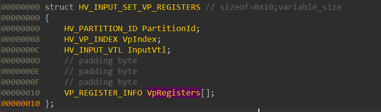
This is the representation of the following scheme according to Hyper-V’s TLFS: 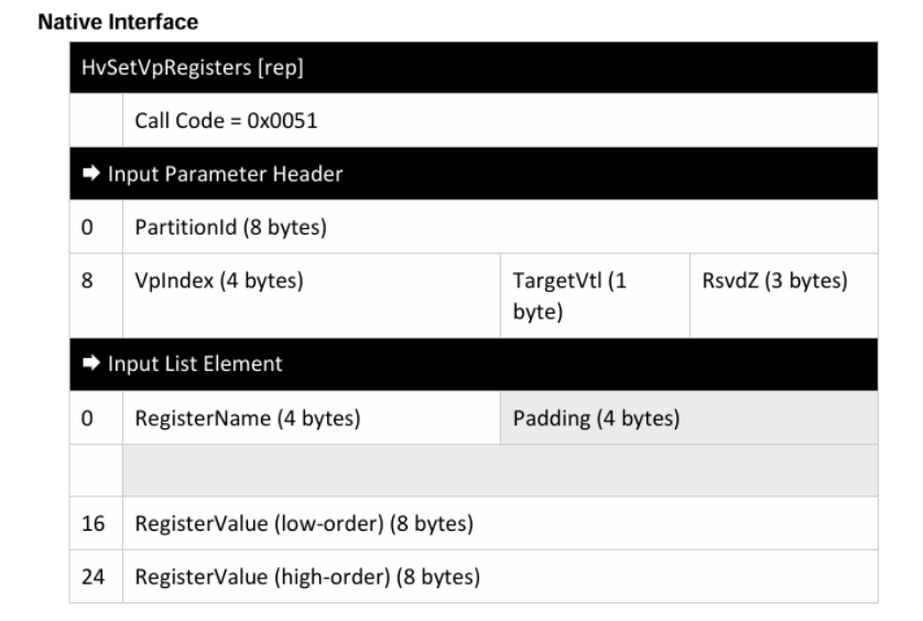
This is how the hypercall input is structured in memory as a rep-hypercall:
1
2
3
4
5
6
7
8
9
10
11
12
+--------------------------------------------+
|      HvCallSetVpRegisters() Parameter      |
|         Headers (16 [0x10] bytes)          |
+--------------------------------------------+
|   Input List Element 0 (32 [0x20] bytes)   |
+--------------------------------------------+
|   Input List Element 1 (32 [0x20] bytes)   |
+--------------------------------------------+
|                   ...                      |
+--------------------------------------------+
|   Input List Element N-1 (32 [0x20] bytes) |
+--------------------------------------------+
1
Note: All of the functions which are not explicitly hypercalls and structs that aren't documented, were named by me. Since these are not an official names they can be named differently from one source to another.
Since this hypercall is one of the core hypercalls in Hyper-V, it has many functions and wrappers around it which are used to handle different VP Registers. I’ll show only the main and interesting parts of the hypercall for the sake of time and length.
Here is the HvCallSetVpRegisters() function within Hyper-V: 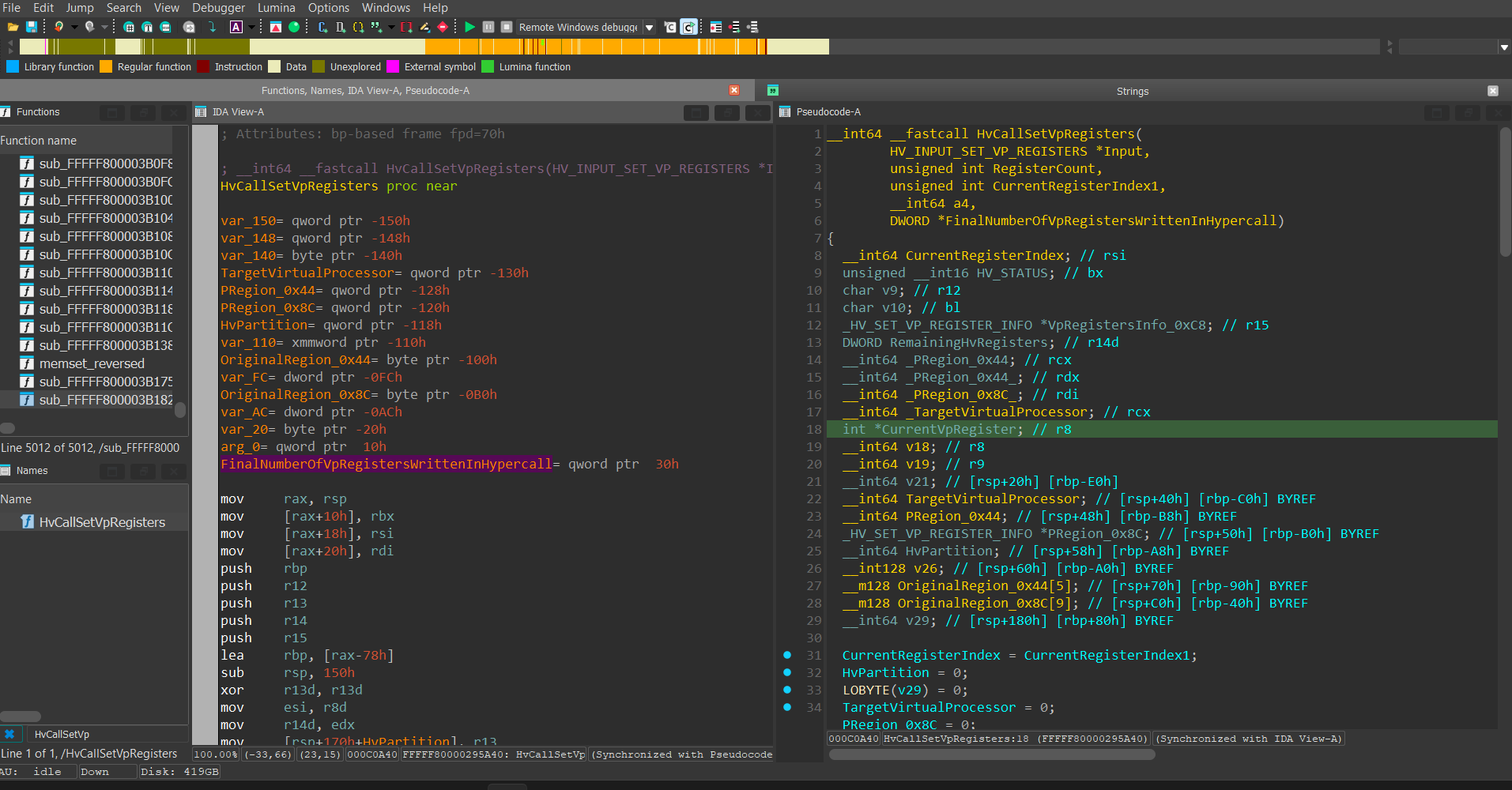
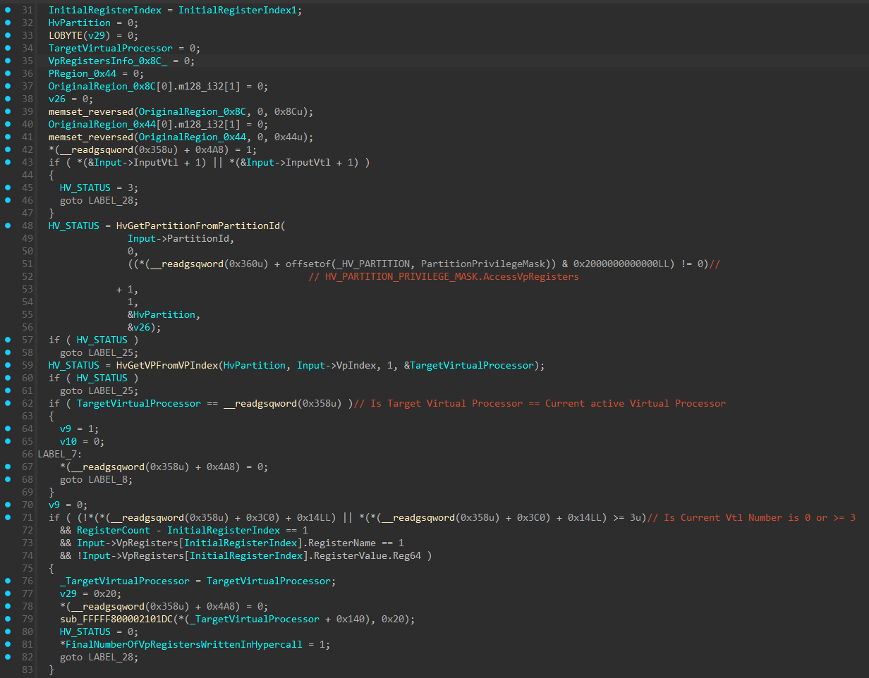
The function starts by allocating 2 structures on the stack, one sized 0x8C and one sized 0x44, and memsets them to 0.
Next, the function attempts to locate 2 critical structures. The first one is the target Virtual Processor structure’s base address (which I named HV_VP) using the VP Index retrieved in the hypercall arguments. This is done through a function called HvGetVpFromVpIndex().
The second one is the target Partition structure’s base address (which I named HV_PARTITION) based on the Partition ID retrieved in the hypercalls arguments. This is also done through a function similar to HvGetVpFromVpIndex() that’s called HvGetPartitionFromPartitionId().
The function continues and performs certain sanity checks, and after that starts to construct the 0x8C sized structure allocated on the stack:
The structure (which I named VpRegistersInfo) holds information used to track the execution state of writing to the VP Registers, such as:
OperationType- This field is used in theHvGenericOperationHandler()function and serves as the operation type handler index. Will be explained soon.InputVtl- The target VTL number in which the hypercall will be executed on.NumberOfVpRegistersWrittenInHypercall- Will hold (at the end of the hypercall execution) the total number of VP registers that were written during the hypercall execution. If an error occured during the execution, this field will hold the number of VP registers that the hypercall writed to until the error occured. In a successful execution, this field is supposed to be equal to theNumberOfVpRegistersInHypercallfield.NumberOfVpRegistersInHypercall- Holds the number of virtual registers the hypercall intends to write to.CallerHvPartition- Holds a pointer to the currentHV_PARTITIONstructure from which the hypercall was called from. This structure is an undocumented structure that represents a Partition and can be retreived from__readgsqword(0x360).VpRegistersInputListBaseAddress- Holds the base address of the hypercall’s Input list.CallerVtlNumber- The Vtl Number from which the hypercall was invoked from.
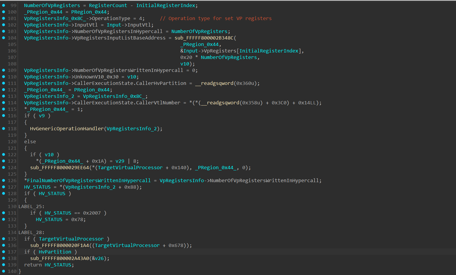
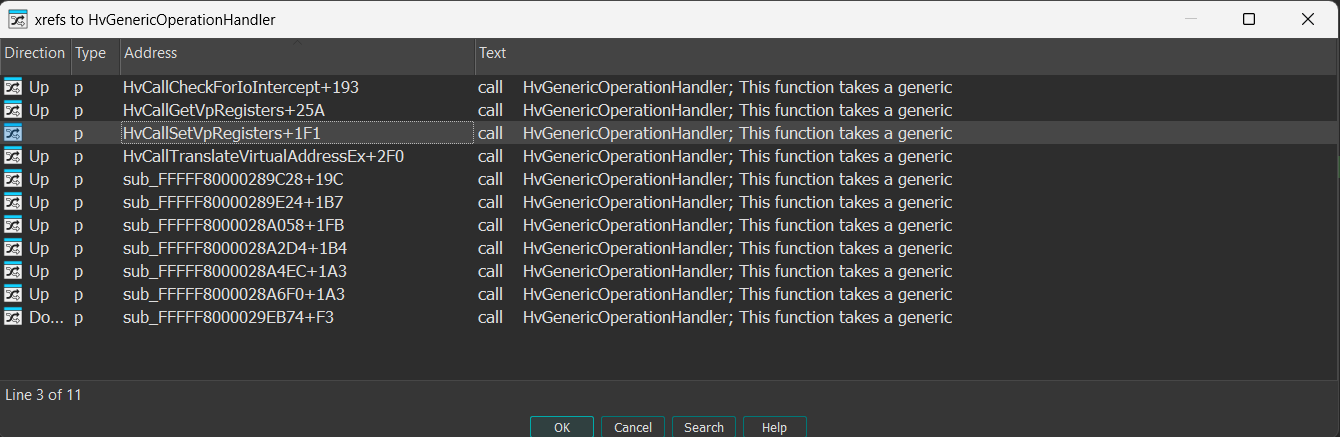
At line 118, HvGenericOperationHandler() is invoked and passes a pointer to the VpRegistersInfo structure as an argument.
The HvGenericOperationHandler() is a big function that has multiple cross references:
The first argument of HvGenericOperationHandler() is a generic structure pointer that seems to be casted differently based on the given operation type passed as the first field in the structure. In the case of HvcallSetVpRegisters(), the OperationType is 4, as can be seen in the VpRegistersInfo reversed structure.
The HvGenericOperationHandler() function holds multiple handling mechanisms for multiple hypercalls and scenarios. Based on the operation type, the function invokes the relevant handler.
The handler for HvCallSetVpRegister() operation code is HvSetVpRegistersOperationHandler() and it’s invoked here: 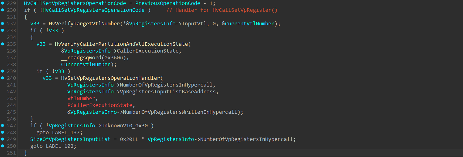
The HvSetVpRegistersOperationHandler() function: 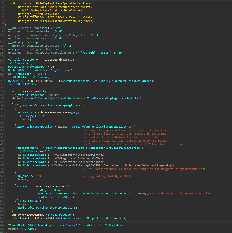
The HvSetVpRegistersOperationHandler() function performs the actual iteration over the hypercall input list in a while loop and invokes HvSetVpRegistersMain() for each virtual register.
The HvSetVpRegistersMain() performs some sanity checks on the HvRegisterName value passed to it, and then invokes HvWriteToVpRegisterHandler(): 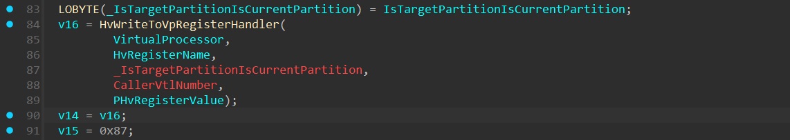
The HvWriteToVpRegisterHandler() function: 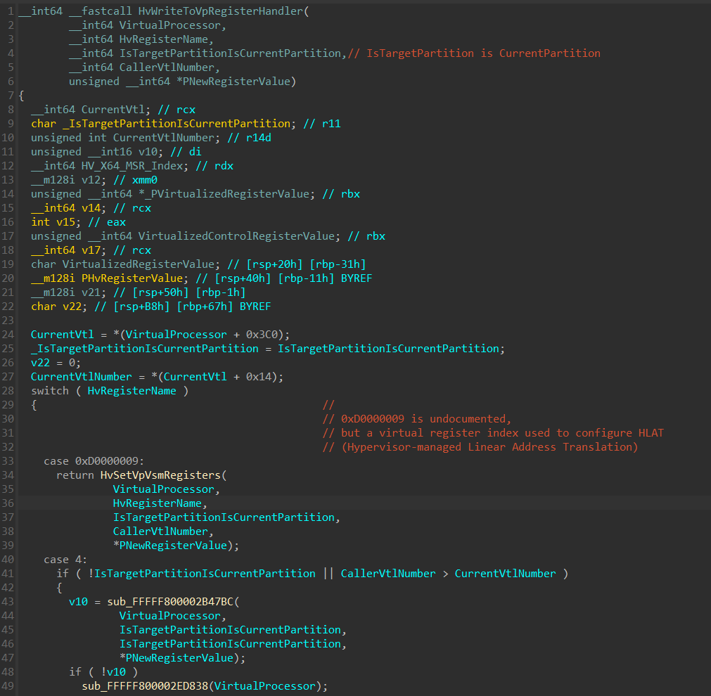
In the HvWriteToVpRegisterHandler() there’s a switch/case on the HvRegisterName, and based on the value, a relevant handler function will be invoked.
Note that there are A LOT of virtual registers handlers, so I’ll cover only VSM registers handlers.
Virtual Secure Mode Registers
As said before, one of the reasons for having a Virtual Processor State (for each VTL) is to have a complete picture about the VTL execution state, including states related to internal Hyper-V mechanisms that aren’t tracked or implemented on the hardware side.
Some of the interesting registers are the ones related to VSM (Virtual Secure Mode).
Here are some of the Virtual Processor registers related to Virtual Secure Mode:
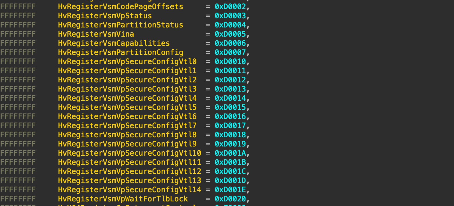
1. HvRegisterVsmVpSecureConfigVtl
The HvRegisterVsmVpSecureConfigVtl virtual registers are used to determine a VSM configuration for each VTL. Some of the mechanisms configured from this register is MBEC (Mode-Based Execution Control) , Supervisor Shadow Stack (KCET) and HLAT (Hypervisor-Managed Linear Address Translation). It’s undocumented that both HLAT and KCET are fields in this virtual register, but we’ll soon see it when reversing some of the functions.
Every VTL holds instances of VSM Secure Config for every VTL lower than the current VTL. This means that VTL2 will hold within it the secure config of VTL1 and the secure config of VTL0. It’s important to note it during the reversing
According to microsoft’s documentation, to make use of Mode-based execution control, it must be enabled at two levels:
When the VTL is enabled for a partition, MBEC must be enabled using
HvCallEnablePartitionVtl().MBEC must be configured on a per-VP and per-VTL basis, using
HvRegisterVsmVpSecureConfigVtlXandHvRegisterVsmVpStatus.
This structure is partially documented, but I managed to fully reverse it (as much as I know) into the following structure:
1
2
3
4
5
6
7
8
struct _HV_REGISTER_VSM_VP_SECURE_VTL_CONFIG
{
    UINT64 MbecEnabled : 1;                     // bit 0
    UINT64 TlbLocked : 1;                       // bit 1
    UINT64 SupervisorShadowStackEnabled : 1;    // bit 2 <-- Undocumented
    UINT64 HvptEnabled : 1;                     // bit 3 <-- Undocumented
    UINT64 Reserved : 60;                       // bits 4–63
};
2. HvRegisterVsmCapabilities
A virtual register used to determine certain VSM Capabilities and is constructed as the following:
1
2
3
4
5
6
7
struct HV_X64_REGISTER_VSM_CAPABILITIES // sizeof=0x8
{
unsigned __int64 RsvdZ : 46;
unsigned __int64 DenyLowerVtlStartup : 1;
unsigned __int64 MbecVtlMask : 16;
unsigned __int64 Dr6Shared : 1;
};
Dr6Shared - Indicates to the guest whether the DR6 register is a shared register between the VTLs.
MbecVtlMask - Indicates to the guest the VTLs for which MBEC can be enabled.
DenyLowerVtlStartup - Indicates to the guest whether a VTL can deny a VP reset by a lower VTL.
3. HvX64RegisterCrInterceptControl
A virtual registers that enables Secure Register Intercepts. Secure Intercepts is one of the strongest features in Virtualization Based Security.
Secure Intercepts is a mechanism that allows to intercept certain operations and track it from a higher VTL, in this case VTL 1. This mechanism is widely used by HyperGuard to capture sensitive MSR Read/Write, Control Registers Read/Write and more.
More on the Secure Intercepts topic can be found here:
The HvX64RegisterCrInterceptControl is a bitmask that determines to which operation an Intercept will be invoked to, and is constructed as the following:
1
2
3
4
5
6
7
8
9
10
11
12
13
14
15
16
17
18
19
20
21
22
23
24
25
26
27
28
29
30
31
32
33
typedef union
{
    UINT64 AsUINT64;
    struct
    {
        UINT64 Cr0Write : 1;
        UINT64 Cr4Write : 1;
        UINT64 XCr0Write : 1;
        UINT64 IA32MiscEnableRead : 1;
        UINT64 IA32MiscEnableWrite : 1;
        UINT64 MsrLstarRead : 1;
        UINT64 MsrLstarWrite : 1;
        UINT64 MsrStarRead : 1;
        UINT64 MsrStarWrite : 1;
        UINT64 MsrCstarRead : 1;
        UINT64 MsrCstarWrite : 1;
        UINT64 ApicBaseMsrRead : 1;
        UINT64 ApicBaseMsrWrite : 1;
        UINT64 MsrEferRead : 1;
        UINT64 MsrEferWrite : 1;
        UINT64 GdtrWrite : 1;
        UINT64 IdtrWrite : 1;
        UINT64 LdtrWrite : 1;
        UINT64 TrWrite : 1;
        UINT64 MsrSysenterCsWrite : 1;
        UINT64 MsrSysenterEipWrite : 1;
        UINT64 MsrSysenterEspWrite : 1;
        UINT64 MsrSfmaskWrite : 1;
        UINT64 MsrTscAuxWrite : 1;
        UINT64 MsrSgxLaunchControlWrite : 1;
        UINT64 RsvdZ : 39;
    };
} HV_REGISTER_CR_INTERCEPT_CONTROL;
Another interesting registers related to this virtual register are HvX64RegisterCrInterceptControl, HvX64RegisterCrInterceptCr0Mask, HvX64RegisterCrInterceptCr4Mask, HvX64RegisterCrInterceptIa32MiscEnableMask.
These registers serve as a bitmask that provides per-bit control over which write operations within the CR0/CR4 bitmask will result in an intercept.
For example, if bit 20 is set in HvX64RegisterCrInterceptCr4Mask. Any attempt to flip bit 20 (SMEP bit) within the CR4 will invoke an intercept.
4. HvRegisterVsmVpStatus
A read only virtual register that’s shared across all VTLs. This virtual register is a per-VP register, meaning each virtual processor maintains its own instance. The register provides information about which VTLs have been enabled, which is active, as well as the whether MBEC is active on a Virtual Processor.
HvRegisterVsmVpStatus is constructed as the following:
1
2
3
4
5
6
7
8
struct HV_REGISTER_VSM_VP_STATUS
{
    UINT64 ActiveVtl : 4;
    UINT64 ActiveMbecEnabled : 1;
    UINT64 Reserved0 : 11;
    UINT64 EnabledVtlSet : 16;
    UINT64 Reserved1 : 32;
};
ActiveVtl- The ID of the VTL context that is currently active on the Virtual Processor.ActiveMbecEnabled- specifies that MBEC is currently active on the Virtual processor.EnabledVtlSet- A bitmap of the VTLs that are enabled on the Virtual Processor.
Since it’s a read-only virtual register, we won’t see it in HvCallSetVpRegister(), but it’s seen in another function executed during HvCallGetVpRegister() hypercall:
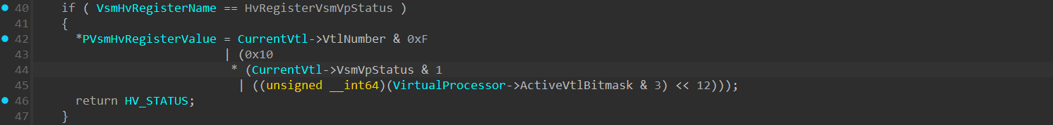
As we can see, a base value of HvRegisterVsmVpStatus is saved within the HV_VTL structure. When an attempt to read the real register value, a set of bitwise operations are performed to retreive the real value.
The internal value of VsmVpStatus field within the VTL is another internal bitmask, which I didn’t reversed.
A C function that resolves the known VsmVpStatus value:
1
2
3
4
ULONG64 VsmVpStatusTranslator(BYTE InternalVtlVsmVpStatus, DWORD ActiveVtlBitMask, BYTE CurrentVtlNumber)
{
	return CurrentVtlNumber & 0xF | (0x10 * (InternalVtlVsmVpStatus & 1 | ((ActiveVtlBitMask & 3) << 12)));
}
5. HvRegisterVsmCodePageOffsets
A virtual register that holds offsets from the hypercall page base address (which is mapped both in hyper-v and in guest partitions) to VTL Call and VTL Return assembly stubs and is used when VTL-Call and VTL-Return operations. This is a read-only and partition-wide register, with a separate instance per-VTL.
HvRegisterVsmCodePageOffsets is constructed as the following:
1
2
3
4
5
6
struct HV_REGISTER_VSM_CODE_PAGE_OFFSETS
{
    UINT64 VtlCallOffset : 12;
    UINT64 VtlReturnOffset : 12;
    UINT64 ReservedZ : 40;
};
HvRegisterVsmCodePageOffsets value is initialized in the following code into 2 globals I called g_HvVsmCodePageOffsets32 and g_HvVsmCodePageOffsets64:

These are the assembly stubs of the HvCallVtlCall and HvCallVtlReturn hypercalls (located in the .data section of Hyper-V) that are used in the code above:
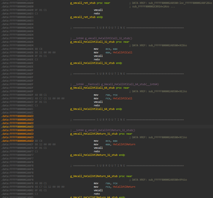
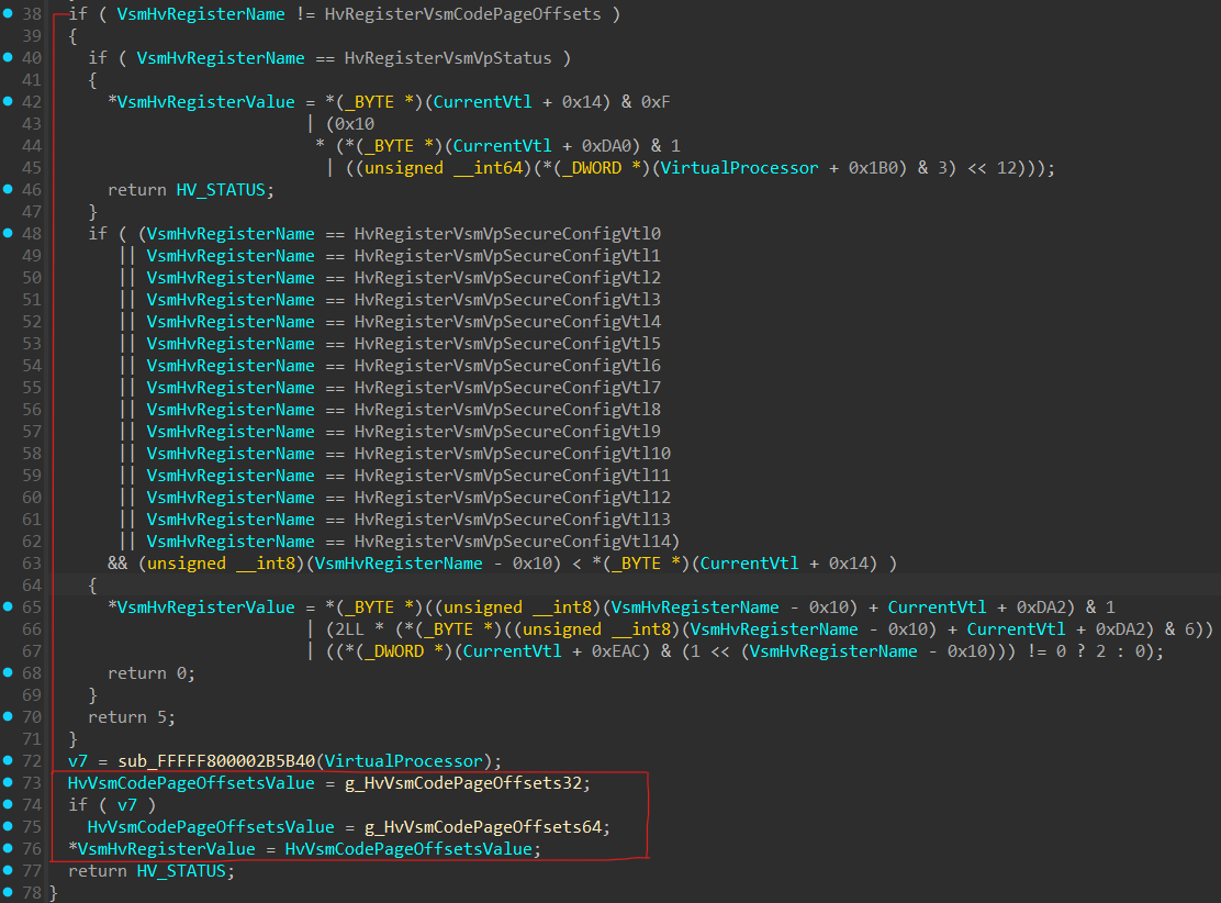
When HvCallGetVpRegister() hypercall is invoked with a virtual register of HvRegisterVsmCodePageOffsets (0xD0002), one of these global variables will be returned as the virtual register value, as can be seen in this function called during the flow of HvCallGetVpRegister() hypercall:
In the Secure Kernel, the ShvlpInitializeVsmCodeArea() function is responsible for initializing ShvlpVtlReturn and ShvlpVtlCall global variables, by performing a HvCallGetVpRegister() hypercall (using the ShvlGetVpRegister() wrapper function), saves the result to HvRegisterVsmCodePageOffsets, performs the required bitshifting if required, and appends it to ShvlpHypercallCodePage: 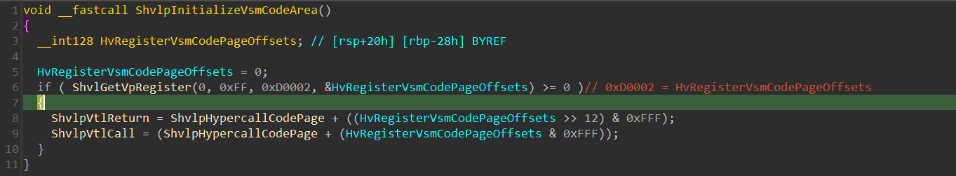
6. HvRegisterVsmPartitionConfig
A virtual register used to configure partition-wide VSM attributes. There is one instance of this register for each VTL (greater than 0) on every partition.
Every VTL can modify its own instance of HV_REGISTER_VSM_PARTITION_CONFIG, as well as instances for lower VTLs. VTLs may not modify this register for higher VTLs.
1
2
3
4
5
6
7
8
9
10
struct HV_REGISTER_VSM_PARTITION_CONFIG
{
    UINT64 EnableVtlProtection : 1;
    UINT64 DefaultVtlProtectionMask : 4;
    UINT64 ZeroMemoryOnReset : 1;
    UINT64 DenyLowerVtlStartup : 1;
    UINT64 ReservedZ : 2;
    UINT64 InterceptVpStartup : 1;
    UINT64 ReservedZ : 54;
};
Enable VTL Protections - Once a VTL has been enabled, the EnableVtlProtection flag must be set before it can begin applying memory protections. This flag is write-once, meaning that once it has been set, it cannot be modified.
Default Protection Mask -
By default, the system applies RWX protections (in the SLAT) to all currently mapped pages, and any future “hot added” pages. A higher VTL can set a different default memory protection policy by specifyingDefaultVtlProtectionMaskinHV_REGISTER_VSM_PARTITION_CONFIG. This mask must be set at the time the VTL is enabled. It cannot be changed once it is set, and is only cleared by a partition reset.An interesting article by Satoshi Tanda and Andrea Alievi called Hunting down the HVCI bug in UEFI mentioning a vulnerability related to a misconfiguration of the
DefaultVtlProtectionMask.ZeroMemOnReset - is a bit that controls if memory is zeroed before a partition resets.
DenyLowerVtlStartup - The DenyLowerVtlStartup flag controls if a virtual processor may be started or reset by lower VTLs.
7. HvRegisterVsmPartitionStatus
HvRegisterVsmPartitionStatus is a per-partition read-only register that is shared across all VTLs.
This register provides information about which VTLs have been enabled for the partition, which VTLs have MBEC enabled, as well as the maximum VTL allowed.
1
2
3
4
5
6
7
 struct HV_REGISTER_VSM_PARTITION_STATUS
{
    UINT64 EnabledVtlSet : 16;
    UINT64 MaximumVtl : 4;
    UINT64 MbecEnabledVtlSet: 16;
    UINT64 ReservedZ : 28;
};
With that knowledge, let’s return to HvWriteToVpRegisterHandler().
In line 288 in HvWriteToVpRegisterHandler() function, there are 2 nested if statements that checks whether the HvRegisterName falls under the VSM registers:
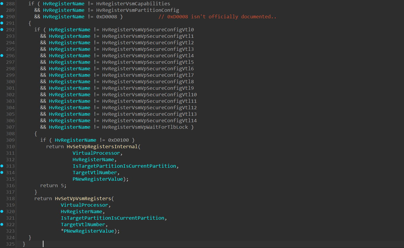
If the operation intends to write to one of the VSM registers, execution will continue to HvSetVpVsmRegisters().
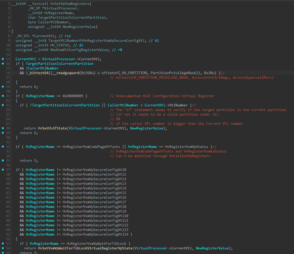
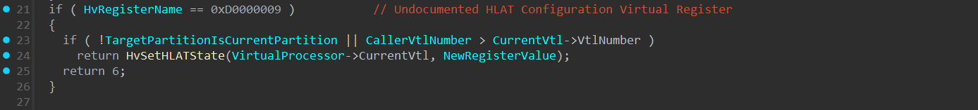
At line 21 in the image above, there’s an if statement that checks if HvRegisterName is 0xD0000009, which is an undocumented virtual register used to configure HLAT (Hypervisor Linear Address Translation) by calling the HvSetHLATState() function. Since HLAT has its own section in the article, I’ll currently skip it and will return to it soon.
Next, we can see there are 2 if statements that seems to be similar to what we’ve seen previously in HvWriteToVpRegisterHandler(), which seems to be an additional check related to the virtual register:
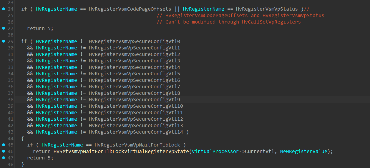
After verifying the registers are indeed related to Virtual Secure Mode, the following is performed:
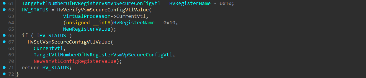
At line 61, TargetVtlNumberOfHvRegisterVsmVpSecureConfigVtl is a byte sized variable of HvRegisterName - 0x10.
This is done in order to extract the target VTL number secure config in HvRegisterVsmVpSecureConfigVtlX from the HvRegisterName.
For example:
1
HvRegisterVsmVpSecureConfigVtl1 = 0xD0011
1
2
3
0xD0011-0x10 = 0xD0001

least significant byte from 0xD0001 is 0x01 -> meaning VTL 1
Next, HvVerifyVsmSecureConfigVtlValue() performs integrity checks on the secure config’s target VTL Number.
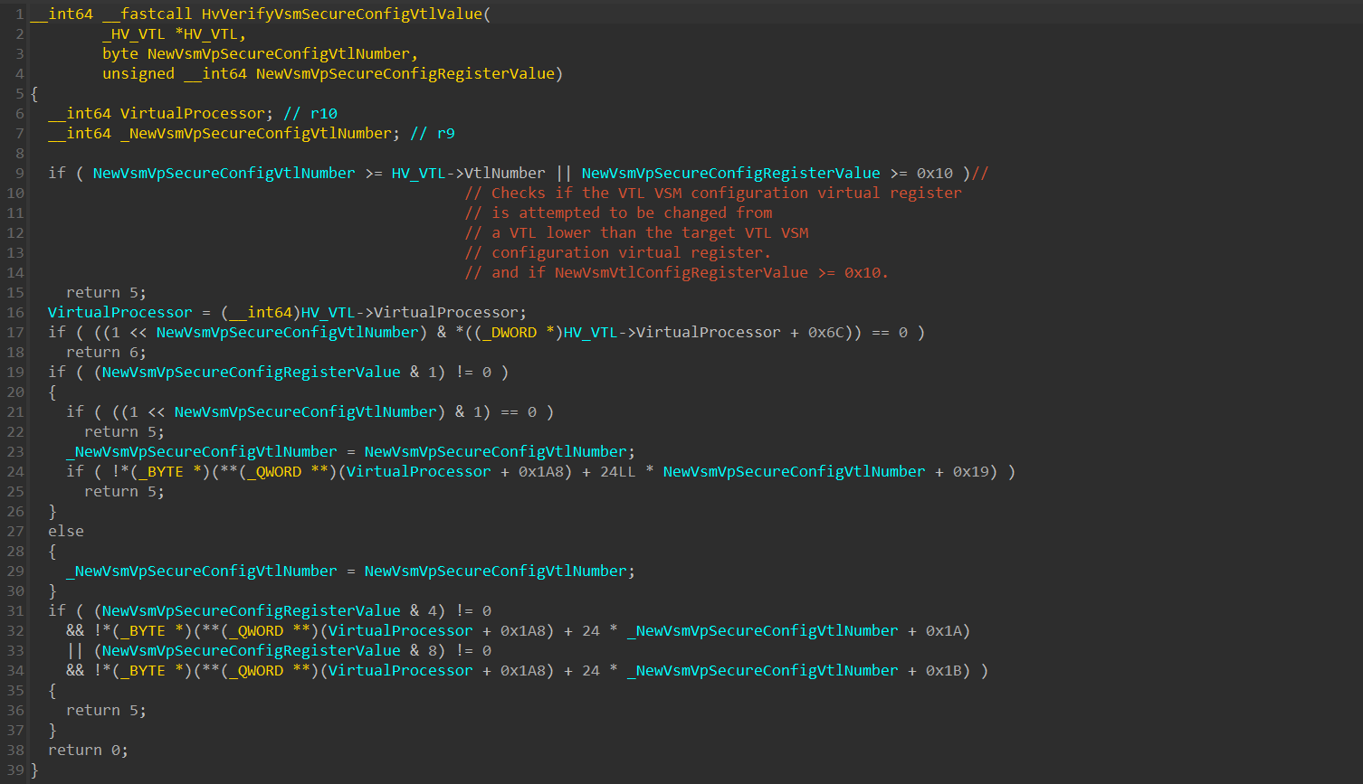
One of the checks verifies that the Secure Config VTL number is lower than the current VTL number that’s currently running.
This check is performed to prevent writing to the current VTL or to a higher VTL’s VSM secure config from a lower VTL. It makes sense, since we previously said that a VTL only holds the secure configs of every VTL that’s lower than him (not even it’s own).
The second part of the first check verifies that the size of NewRegisterValue is lower than 0x10. This allows us to assume that the Secure Config VTL bitmask is consisted out of only 4 bit-sized fields, since 0xF (0b1111) is the highest number allowed.
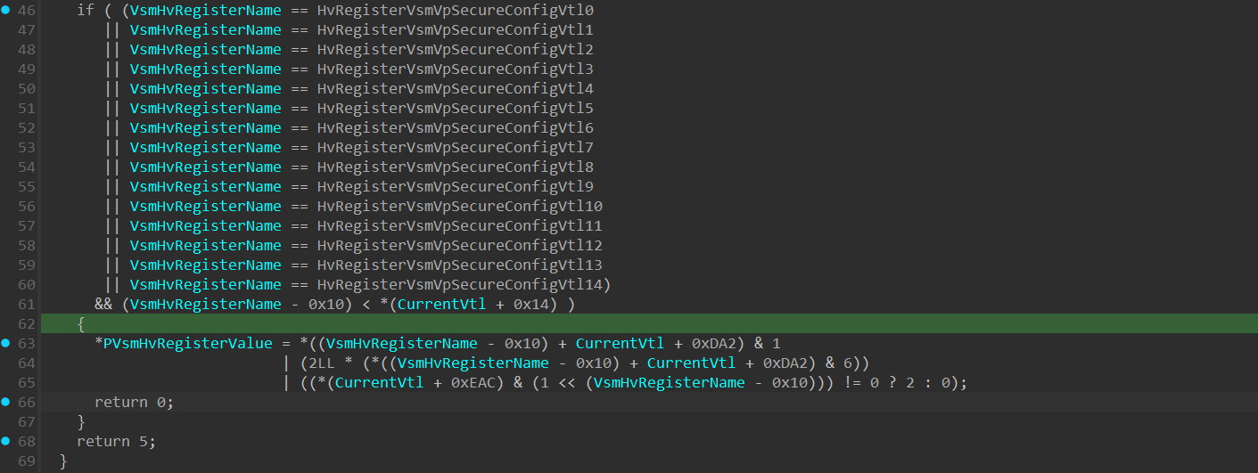
If the checks were passed and HvVerifyVsmSecureConfigVtlValue() returned 0, a call to HvSetVsmSecureConfigVtlValue() is executed:
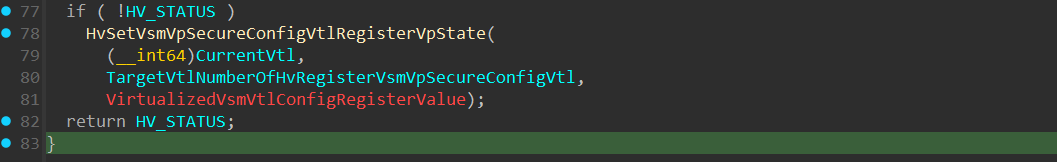
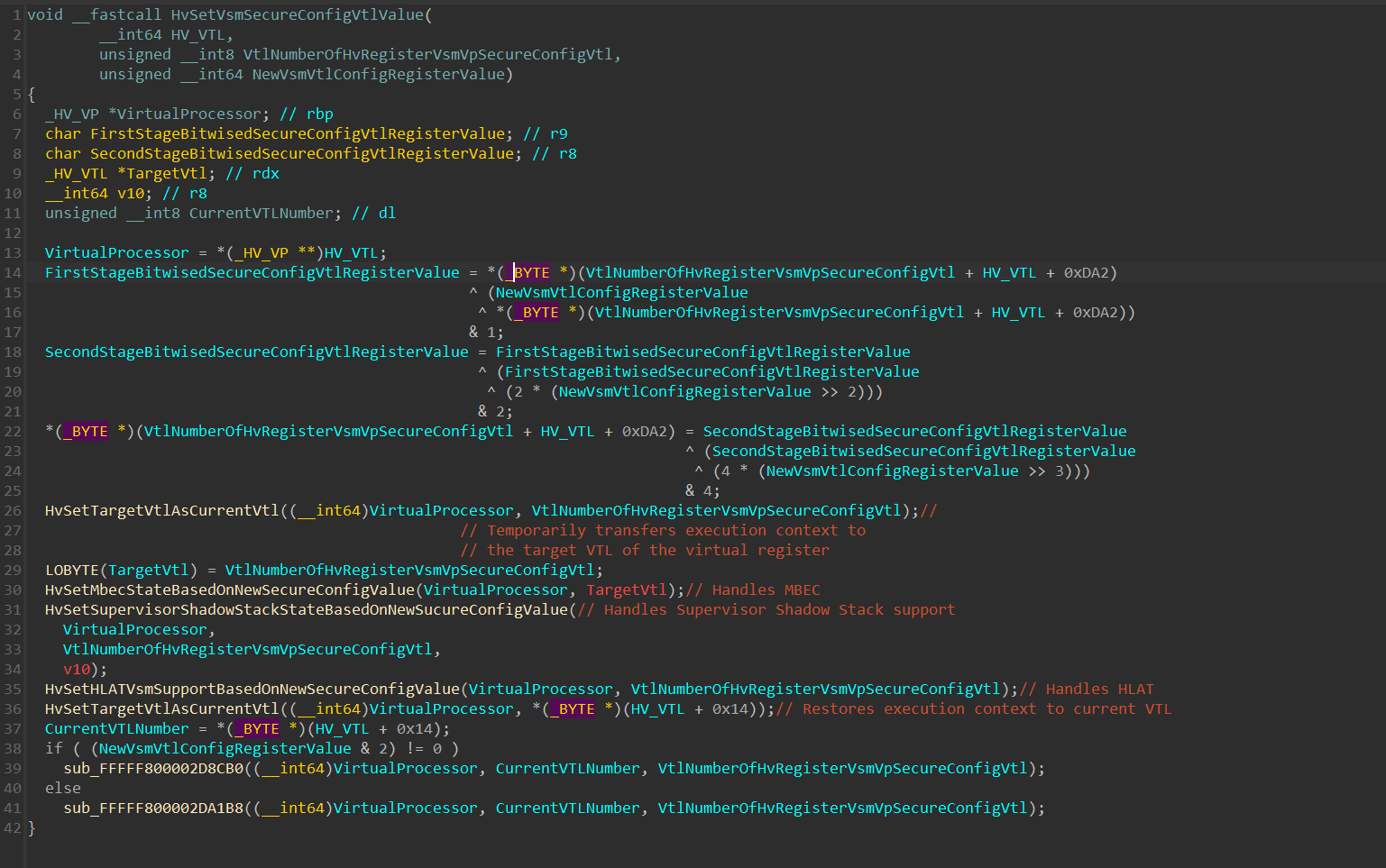
This function is a key function which we’ll return to multiple times during the article, since it not only sets the VSM register value, but also performs the necessary operations to enforce MBEC, KCET (Supervisor Shadow Stack), and HLAT on the VTL, based on the given VSM register value.
The function performs multiple bitwise operations on the Virtual Register Value, and then write the new VSM secure config value to HV_VTL+0xDA2+VtlNumberOfHvRegisterVsmVpSecureConfigVtl.
HV_VTL+0xDA2 is the base address of an array of HvRegisterVsmVpSecureConfigVtl registers within the HV_VTL structure.
1
2
3
HvRegisterVsmVpSecureConfigVtl0 is at *(HV_VTL+0xDA2+0x00)
HvRegisterVsmVpSecureConfigVtl1 is at *(HV_VTL+0xDA2+0x01)
etc...
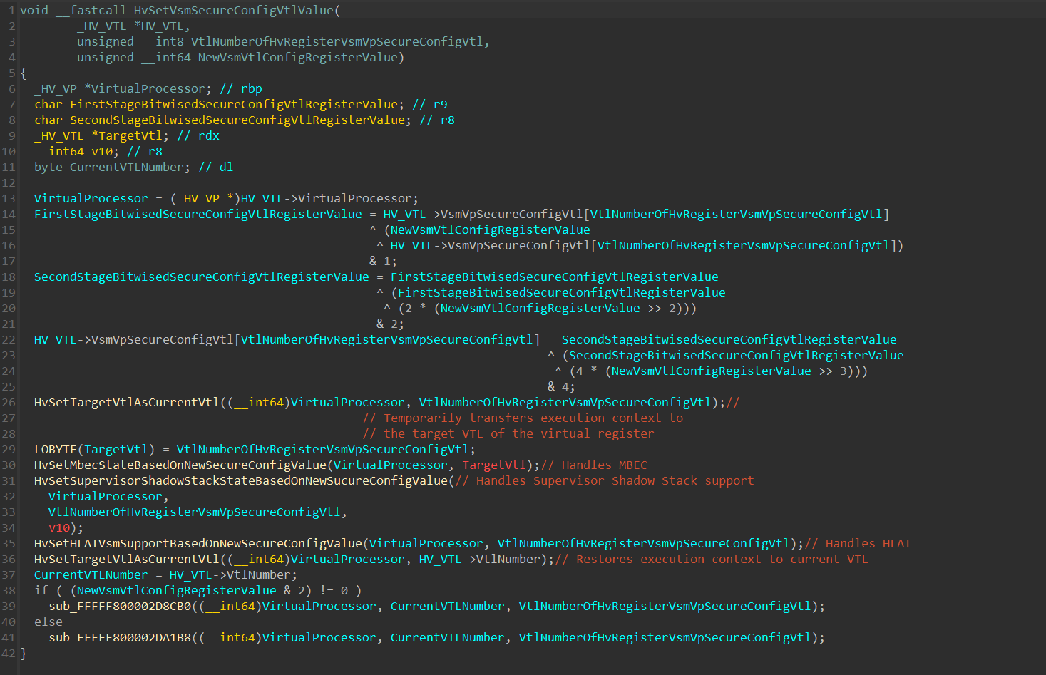
With that understanding, here is an updated version of the function:
Since multiple arithmetic and bitwise operations are performed on the new register value, it’s important to understand that the value saved within the HV_VTL+0xDA2+VtlNumberOfHvRegisterVsmVpSecureConfigVtl - Doesn’t hold directly the “real” bitmask value of the _HV_REGISTER_VSM_VP_SECURE_VTL_CONFIG structure we’ve seen previously .
In order to restore it to the original value, we’ll see how it’s retreived from invoking a HvCallGetVpRegister() hypercall:
which can be simplified into the following function:
1
2
3
4
5
6
7
8
9
10
11
12
ULONG64 GetSecureConfigValue(BYTE BaseSecureConfigValue, DWORD IsTlbLockedSet, BYTE VsmVtlNumber)
{
    /*
        * IsTlbLockedSet -> sets if the TlbLocked is enabled (2nd bit in the secure config bitmask).

        * BaseSecureConfigValue -> the value in *(HV_VTL+0xDA2+TargetVtlNumber)

        * VsmVtlNumber -> The VTL Number of the secure config.
    */
	return BaseSecureConfigValue & 1 | (2LL * (BaseSecureConfigValue & 6))
        | ((IsTlbLockedSet & (1 << VsmVtlNumber)) != 0 ? 2 : 0);
}
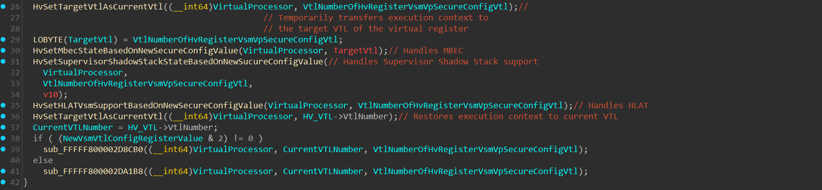
Returning to HvSetVsmSecureConfigVtlValue(), after setting the new register value, execution switches to the VTL that has it’s VSM Secure Config VTL value changed (which must be a lower VTL than the current one, as it’s already said that a VTL can only change the VSM secure config of a VTL lower than itself).
At line 35, there’s a call to HvSetHLATVsmSupportBasedOnNewSecureConfigValue(), which we’ll soon return to in the HLAT section:
HLAT - Hypervisor Linear Address Translation
HLAT (also known as HVPT by microsoft) is a hardware security feature that lets the hypervisor protect guest OS memory by enforcing its own secure page tables, mitigating Remapping Attacks and Aliasing Attacks. Microsoft officially added support for HVPT in Hyper-V Since 24H2.
If you’re unfamiliar with the basics of HLAT, I highly recommend to get familiar with the topic by reading the 2 articles by Satoshi Tanda before continuing:
- Intel VT-rp - Part 1. remapping attack and HLAT
- Intel VT-rp - Part 2. paging-write and guest-paging verification
The state of HLAT is managed on multiple fronts:
- Hardware level -
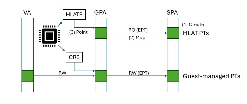
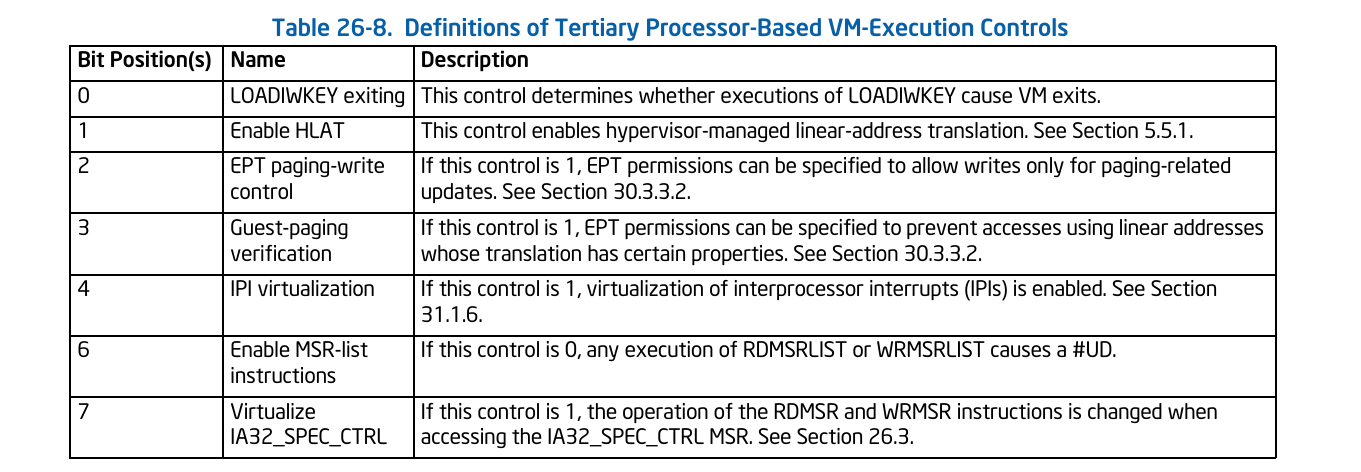
HLAT is enabled/disabled through the “Enable HLAT” bit within the Tertiary VM-Execution Control field in the VMCS.
HLATP - The HLATP is the base physical address of the HLAT-managed paging structures (the equivalent of CR3, but for HLAT translation). This field resides within HLAT_POINTER field (at index: 0x2040) in the VMCS.
HLAT Prefix Size - The HLAT Prefix Size is a field in the VMCS that defines the PLR (Protected Linear Range), which is the range of addresses meant to be protected by HVPT. Checking the HLAT Prefix Size is the first step in the translation process. The HLAT Prefix Size stores the number of most significant bits that should be set to 1 in the address for being translated by HLAT. This field determines whether an address should be translated via HVPT or CR3-rooted page tables.
Guest Paging-Verification (GPV) + EPT paging-write control (PW) - 2 additional mechanisms that are available as part of Intel VT-RP (intel’s Redirection-Protection, which holds under it: HLAT, GPV, PW):
EPT paging-write control (bit index 2 within Tertiary VM-Execution control) is a performance optimization that comes with HLAT that allows setting A/D (Access/Dirty) bits on HLAT Protected pages without a need for VMEXIT even if the PTEs are protected as Read-Only. This is enabled by setting the EPT paging-write control bit to 1, and setting PWA (Paging Write Access) bit to 1 in the EPT paging structures.
Guest Paging-Verification (GPV) - A mitigation that goes along with HLAT that verifies that each paging structure used during address translation comes from HLAT’s PLR. This is enforced by setting the VGP (Verify Guest Paging) bit in the EPT. When set, each paging structure used during the address translation in the EPT will be checked for having the PW (Paging-Write) bit set within it.
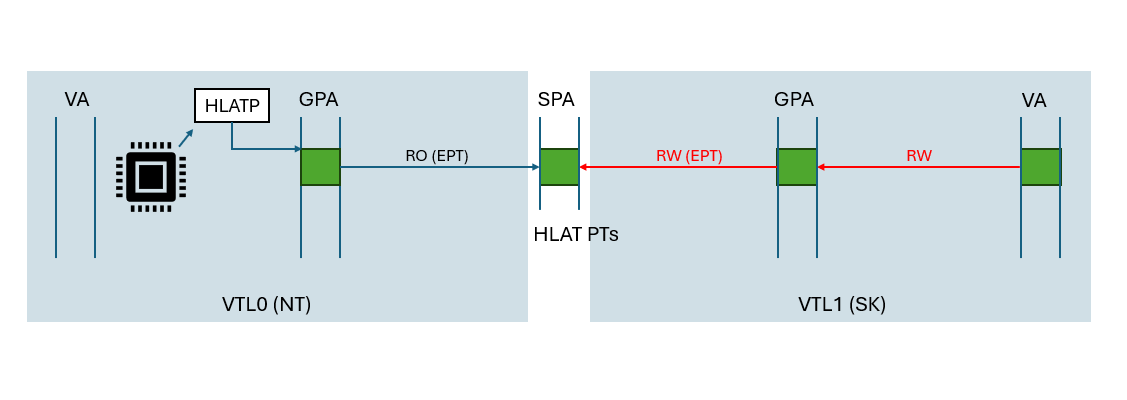
- Software Level -
- The HVPT paging structures are mapped in both in VTL0 and VTL1. In VTL0, the HVPT paging structures are mapped as Read-Only, and in VTL1 they are mapped as Read+Write privileges.
 https://github.com/AaLl86/WindowsInternals/blob/master/Slides/Hypervisor-enforced%20Paging%20Translation%20-%20The%20end%20of%20non%20data-driven%20Kernel%20Exploits%20(Recon2024).pdf
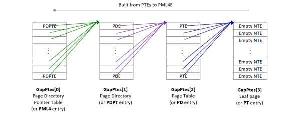
The HVPT paging structures are managed in VTL-1 where each paging structure is structured as NTEs (Normal Table Entry).
NTE is a structure within VTL-1 that was initially used to track the state of private pages in VTL0 from VTL1 (private pages being pages that are accessible through private PTEs, and not prototype PTEs used for section objects).
- In Hyper-V, the HV_VTL structure holds under it multiple fields take parts in configuring HLAT (The names of the fields are given from my reversing):
HardwareHvptEnabled- A boolean field that indicates whether HLAT is set as enabled on the Tertiary VM-Execution Control of the VTL (by setting the “Enable HLAT” bit).SoftwareHvptEnabled- A boolean field that indicates whether HLAT is supported by VSM (by setting theHvptEnabledbit within theHvRegisterVsmVpSecureConfigVtlvirtual register of the VTL).VsmVpSecureConfigVtl- As written above, this virtual register holds a bit that indicates a VSM support of HVPT.ShadowSecureConfigVtl- A field within theHV_VTLthat holds a shadow value of the secure config VTL of the current VTL. This value seems to only be used to tracking the VTL’s secure config state from it’s own structure. Changing the value won’t affect the VSM state of the VTL.TertiaryVmExecutionControls- A field that tracks the current bitmask value of the Tertiary VM-Execution controls of the current VTL’s VMCS. This field resides within an internal structure I called VmcsInfo (HV_VTL->VtlState->VmcsInfo).
- The HVPT paging structures are mapped in both in VTL0 and VTL1. In VTL0, the HVPT paging structures are mapped as Read-Only, and in VTL1 they are mapped as Read+Write privileges.
This research will focus on the Hyper-V’s perspective of handling HLAT.
Previously, we’ve seen the undocumented 0xD0000009 virtual register, which calls the HvSetHLATState() function:
With that understanding, let’s look at HvSetHLATState: 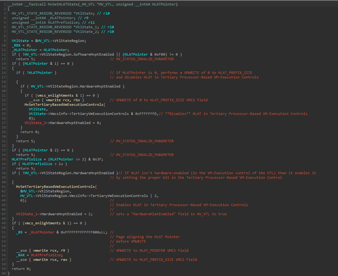
The function starts by verifying that the SoftwareHvptEnabled boolean field in the VtlState structure of the current VTL isn’t 0. Then, performs multiple checks on the HLATPointer.
If the HLAT Pointer attempted to be written to HLATP is 0, and the HardwareHvptEnabled field is set to “1”, a call to HvSetTertiaryBasedVmExecutionControls() will be executed with a value of VtlState->VmcsInfo->TertiaryVmExecutionControls & 0xFFFFFFFD, which disables the “Enable HLAT” bit within the bitmask, and sets the HardwareHvptEnabled field to 0.
The HvSetTertiaryBasedVmExecutionControls() function:
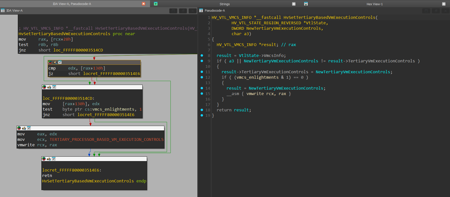
The function verifies that the new value written to the VM-Execution control is different than the current one and then perfoms the actual VMWRITE instruction with the new value.
Returning to HvSetHlatState():
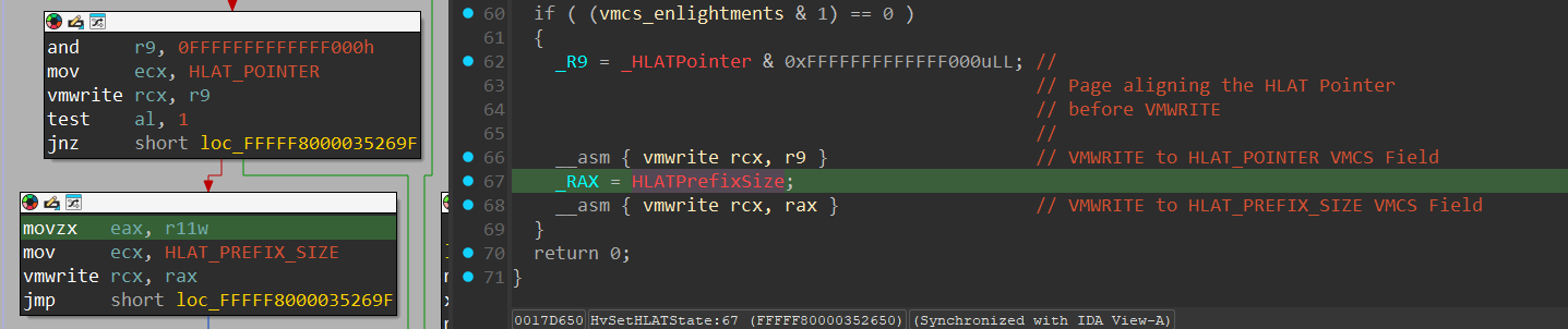
In line 38, after more integrity checks on the HLAT Pointer and the HLAT Prefix Size (which is extracted in line 35), another case is handled where a HLAT Pointer value was given (and SoftwareHvptEnabled is enabled from a check performed at the start of the function), but the “HardwareHvptEnabled” isn’t set to 1. In that case, a call to HvSetTertiaryBasedVmExecutionControls() will be performed to enable HLAT, and update the “HardwareHvptEnabled” to 1.
After everything was handled, 2 VMWRITE operations are pefromed to update the HLAT_POINTER and the HLAT_PREFIX_SIZE VMCS fields:
The next thing we’ll see is how the SoftwareHvptEnabled field is set.
Which is performed in HvSetHLATVsmSupportBasedOnNewSecureConfigValue().
Before explaining this function, it’s important to understand the situation we’re at:
This function is called from the
HvSetVsmSecureConfigVtlValue()that we previously seen, and is called after the new secure config register value was set.We’re now in the execution context of the VTL that has it’s secure config value modified to the new value. The switch also occured in
HvSetVsmSecureConfigVtlValue()after the new secure config register value was set by calling theHvSetTargetVtlAsCurrentVtl().Another reminder that a VTL can’t access it’s own secure config VTL or an higher secure config VTL.
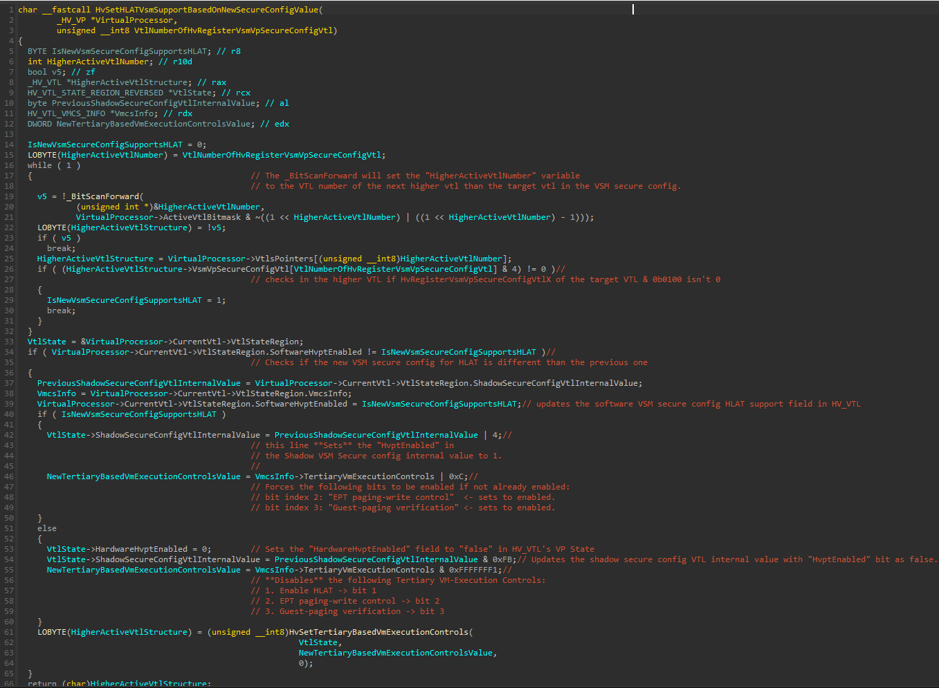
Since we’re in the execution context of the secure config VTL, the function will start by resolving the next higher active VTL in the ActiveVtlBitmask of the Virtual Processor and reading the HV_VTL structure pointer base address of the next higher active VTL from a VTL pointers array that resides within the HV_VP data structure.
Next, at line 26, the function reads the new secure config internal value (it’s internal since we’ve seen that the new Secure Config value is being bitwise manipulated before being stored) from the higher VTL, and AND it with 4.
This checks from the internal value whether the HvptEnabled bit is set.
Let’s view the secure config VTL structure once again:
1
2
3
4
5
6
7
8
struct _HV_REGISTER_VSM_VP_SECURE_VTL_CONFIG
{
    UINT64 MbecEnabled : 1;                     // bit 0
    UINT64 TlbLocked : 1;                       // bit 1
    UINT64 SupervisorShadowStackEnabled : 1;    // bit 2 <-- Undocumented
    UINT64 HvptEnabled : 1;                     // bit 3 <-- Undocumented
    UINT64 Reserved : 60;                       // bits 4–63
};
To verify the the check is actually against the HvptEnabled at index 3, we’ll do the following operation:
1
2
3
4
5
6
7
8
9
10
11
12
13
14
15
16
17
18
19
20
21
22
23
24
25
26
27
28
29
30
31
32
33
34
35

ULONG64 GetSecureConfigValue(DWORD BaseSecureConfigValue, DWORD IsTlbLockedSet, BYTE VsmVtlNumber)
{
    /*
    GetSecureConfigValue() restores from Hyper-V internal value to real value
    and is taken from reversing an internal function called within HvCallGetVpRegister()
    hypercall:
        * IsTlbLockedSet -> sets if the TlbLocked is enabled (2nd bit in the secure config bitmask).

        * BaseSecureConfigValue -> the value in HV_VTL->VsmVpSecureConfig[VsmVtlNumber].

        * VsmVtlNumber -> The VTL Number that the secure config represents.
    */

	return BaseSecureConfigValue & 1 | (2LL * (BaseSecureConfigValue & 6))
        | ((IsTlbLockedSet & (1 << VsmVtlNumber)) != 0 ? 2 : 0);
}

bool IsVsmHvptEnabled(BYTE SecureConfigValue)
{
    /*
        1st argument is the secure config value
        2nd argument we'll set to 0 since we only want to isolate the HLAT bit from the Secure config.
        3rd argument is VTL 0
    */

    // 0x8 == 0b1000 <-- which is the 4th bit that matches the `HvptEnabled` bit
    return (GetSecureConfigValue(SecureConfigValue, 0, 0) & 0x8) != 0;
}

int main()
{
    BYTE SecureConfigValue = 0 | 4; // OR 4 to simulate the "if" statement
    printf("IsVsmHvptEnabled(): %d\n", IsVsmHvptEnabled(SecureConfigValue));
}
Compiling and running: 
With that understanding, let’s continue with the function:
if the if statement is true, it means that there’s a VSM support for HVPT, which is considered a software support for HVPT.
The next interesting if statement is at line 34, which checks if the current software HVPT support value is different from the new software HVPT support:
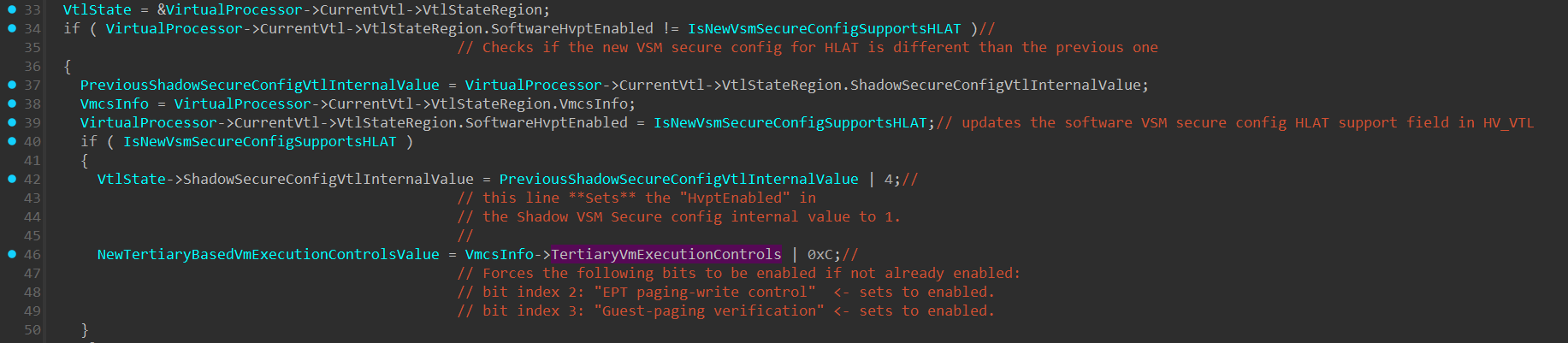
In that case, the following will be performed:
The
ShadowSecureConfigInternalVtlValueis also being OR’ed with 4 to set theHvptEnabledin the shadow secure config value.The
TertiaryVmExecutionControlwithin theVmcsInfostructure will be ORed with 0xC, which enforces “EPT Paging Write” and “Guest Paging Verification” to be enabled. The reason why the “Enable HLAT” bit isn’t set is because currently it’s only software support, and since “HLATP” isn’t filled with any value, there’s no need to set the “Enable HLAT” bit. The “EPT Paging Write” and “Guest Paging Verification” don’t have any special needs like the “Enable HLAT” bit, so enabling them as done here shouldn’t be a problem.
if there’s no “HLAT” support in the new VSM secure config value, then HLAT will be disabled:
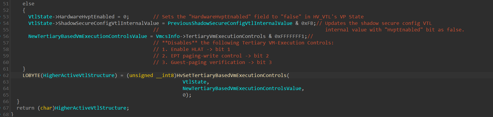
- The “HardwareHvptEnabled” field will be set to 0.
- The “ShadowSecureConfigVtlInternalValue” will be ORed with 0xFB, which will set the “HvptEnabled” field to 0.
And finally, the HvSetTertiaryBasedVmExecutionControls() will be updated accordingly.
The last thing related to HLAT I would like to briefly show is how HLAT state is received using the 0xD0000009 undocumented virtual register.
When invoking a HvCallGetVpRegister() hypercall with HLAT’s virtual register index, execution will get into the following block:
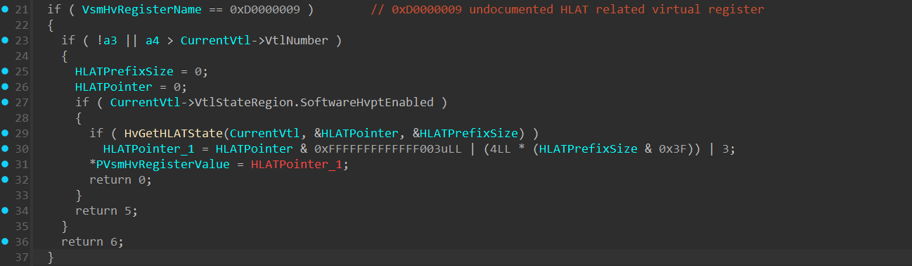
Which, if the conditions are met will invoke a function I named HvGetHLATState():
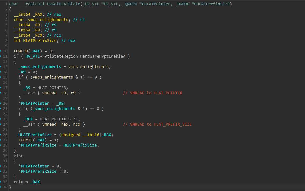
The function first verifies that HardwareHvptEnabled field is set, and than continues to perform 2 VMREAD to HLAT_POINTER and HLAT_PREFIX_SIZE, and return these values
MBEC - Mode Based Execution Control
MBEC is a protection and efficiency mechanism that divides the Executable bit into 2 modes:
User-Mode Executable (XU bit within the EPT) - If the translation of the address specifies user mode (the U/S bit was set in every paging structure entry used to translate the linear address), the resulting Guest Physical Address is executable under EPT only if the XU bit (bit index 10) is set in every EPT paging-structure entry used to translate the Guest Physical Address. This bit in the EPT is only relevant if the MBEC’s enabled bit in the VM-Execution Control is set to 1.
Supervisor Executable (XS bit within the EPT) - If the translation of the address specifies supervisor mode (the U/S bit was clear in the paging-structure entries used to translate the linear address), the resulting Guest Physical Address is executable under EPT only if the XS bit is set in every EPT paging-structure entry used to translate the Guest Physical Address. If the MBEC’s enabled bit in the VM-Execution Control is disabled, this bit will be used as the execute bit for both user-mode and kernel-mode pages.
MBEC is enabled by setting the “Mode-based execute control for EPT” to 1 within the Secondary Processor-Based VM-Execution Controls:

in Hyper-V, MBEC is being tracked and enabled through multiple structures under VSM, which we’ve seen previously:
1
2
3
4
5
6
7
8
9
10
11
12
13
14
15
16
17
18
19
20
21
22
23
24
25
26
27
28
29
30
31
32
33
struct HV_REGISTER_VSM_PARTITION_STATUS
{
    UINT64 EnabledVtlSet : 16;
    UINT64 MaximumVtl : 4;
    UINT64 MbecEnabledVtlSet: 16; // <-- A bitmask that tracks in which VTLs MBEC is enabled.
    UINT64 ReservedZ : 28;
};

struct HV_REGISTER_VSM_VP_STATUS
{
    UINT64 ActiveVtl : 4;
    UINT64 ActiveMbecEnabled : 1; // <-- Tells whether MBEC is enabled on the Virtual Processor.
    UINT64 ReservedZ0 : 11;
    UINT64 EnabledVtlSet : 16;
    UINT64 ReservedZ1 : 32;
};

struct _HV_REGISTER_VSM_VP_SECURE_VTL_CONFIG
{
    UINT64 MbecEnabled : 1;         // <-- Tells whether MBEC is enabled on the VTL.
    UINT64 TlbLocked : 1;
    UINT64 SupervisorShadowStackEnabled : 1;
    UINT64 HvptEnabled : 1;
    UINT64 Reserved : 60;
};

struct HV_X64_REGISTER_VSM_CAPABILITIES
{
    UINT64 RsvdZ : 46;
    UINT64 DenyLowerVtlStartup : 1;
    UINT64 MbecVtlMask : 16; // <-- Holds a bitmask that tells which VTLs MBEC can be enabled on.
    UINT64 Dr6Shared : 1;
};
To understand how MBEC is enabled on a specific VTL, let’s return to the HvSetVsmSecureConfigVtlValue(), which we’ve already seen multiple times:
It’s important to understand the state we’re at.
The currently executing VTL on the Virtual Processor is the VTL in which it’s secure config VTL value was changed.
The MBEC handling function is performed after the secure config VTL value was changed.
The secure config value of a VTL can only be changed from a VTL higher than the target VTL. This means that the execution was originally at a higher VTL.
Specifically, the function relevant to MBEC is HvSetMbecStateBasedOnNewSucureConfigValue(), which has it’s psudocode messed up:
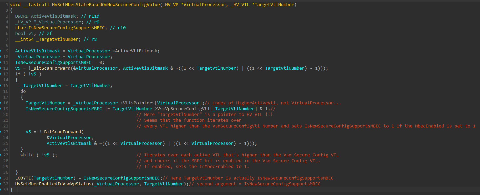
Since the Psuedocode shown in the image above is really messed-up, I’ll explain it with my own words:
The function uses the
BitScanForward()instruction to iterate over the ActiveVtlBitmask field within the Virtual Processor and saves the index of the next active VTL, higher than the currently executing one. (In our case, the next higher VTL will be VTL 1).Next, the function saves the VTL of the next higher VTL in a local variable, and checks whether the first bit is set, if so, sets the
IsNewSecureConfigValueSupportsMbecto 1. The function does that in a loop until it gets to the highest VTL. Currently, since there are only 2 VTLs running, the iteration will stop at VTL1.Finally, the function saves
IsNewSecureConfigValueSupportsMbecinto the Least Significant Byte of a variable and pass it as a second argument to theHvSetMbecEnabledInVsmVpStatus()function.
The HvSetMbecEnabledInVsmVpStatus() function:
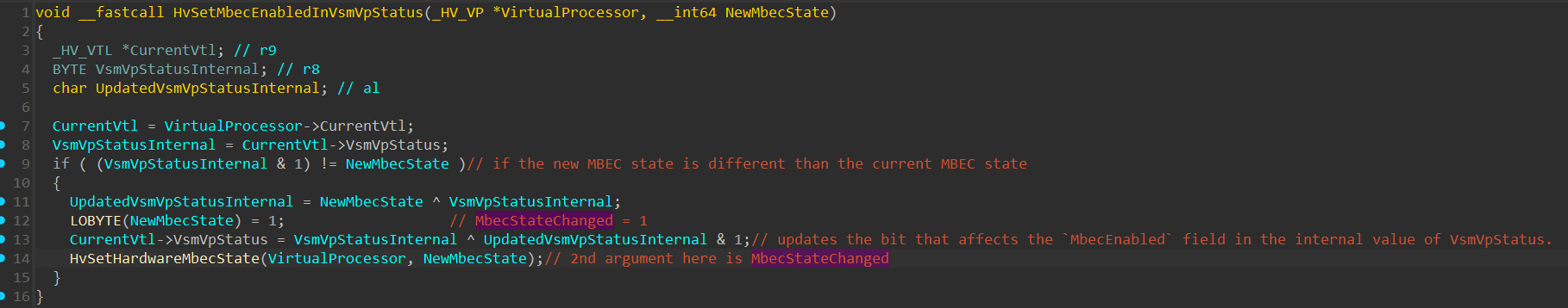
This function checks if the new MBEC state is different than the current one, if so, it updates the bit in the internal VsmVpStatus bitmask that affects the MbecEnabled field of the known VsmVpStatus (which is represented with the HV_REGISTER_VSM_VP_STATUS structure).
It’s important to remember that the VsmVpStatus value saved within the VTL is an internal bitmask, that requires a certain bitwise operations to be executed on it (with multiple other parameters) in order to obtain the known HV_REGISTER_VSM_VP_STATUS structure.
Also, it’s not necessary that all of the fields within the internal bitmask affects the value of the known VsmVpStatus, it might be that some of the fields are only used internally. I named it that way since all of my encounters with that bitmask affected the VsmVpStatus, but that name might not be the most accurate to use.
Next, a call to HvSetHardwareMbecState() is performed:
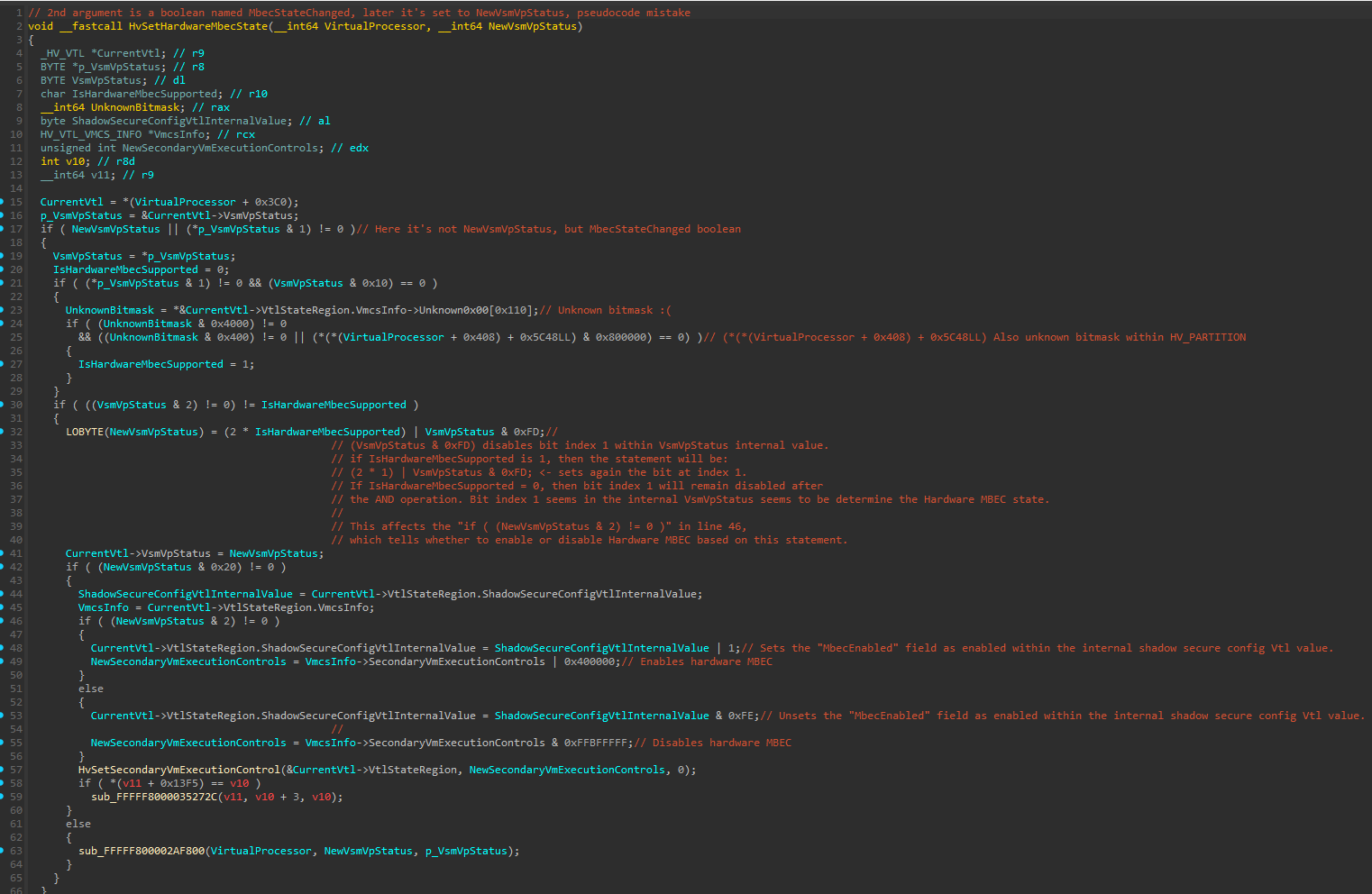
Unfortunately, I wasn’t able to fully reverse this function, so I’ll try to explain it with what I know.
The function starts by performing multiple checks that affect the value of a boolean variable I named IsHardwareMbecSupported - The name isn’t accurate, but at the end it affects the state of MBEC from hardware perspective (when I say “hardware” I mean in the Secondary VM-Execution Control of the VTL’s VMCS), so I decided to name it that way.
This variable takes affect in the following line:
1
LOBYTE(NewVsmVpStatus) = (2 * IsHardwareMbecSupported) | VsmVpStatus & 0xFD
If IsHardwareMbecSupported is set to 1, bit index 1 will be set to 1 in the internal VsmVpStatus bitmask, which will affect the if ( (NewVsmVpStatus & 2) != 0 ) statement to be true:
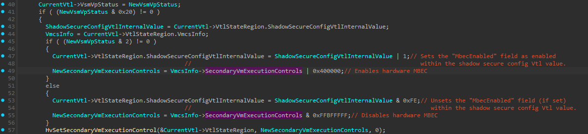
This will enable Hardware MBEC on the VTL context by setting the Mode-based execute control for EPT bit within the Secondary Processor-Based VM-Execution Controls (line 49).
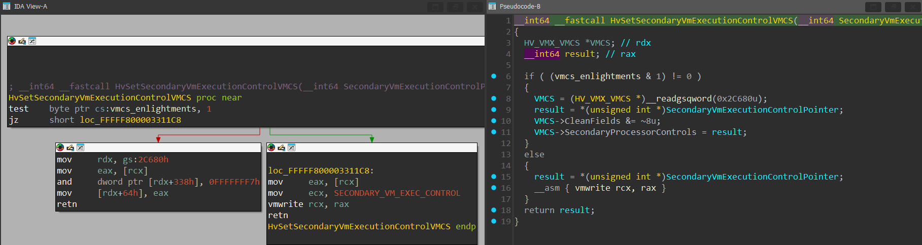
Which will take effect in line 57 by calling the HvSetSecondaryVmExecutionControl() function:
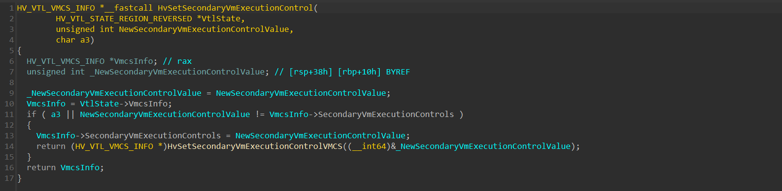
This function calls the HvSetSecondaryVmExecutionControlVMCS, which performs the actual VMWRITE to the Secondary Vm-Execution Control:
The other thing (in line 47 on the image below) that will happen is that the MbecEnabled field will be updated within the shadow secure config VTL value by performing ShadowSecureConfigVtlInternalValue | 1:
else (at line 53), MBEC will be disabled by unsetting the MbecEnabled field within the shadow secure config VTL, and the Mode-based execute control for EPT bit within the Secondary Processor-Based VM-Execution Controls will be set to 0.
That will be it for now, In the next part that I might do in the future, I’ll reverse the handling of Supervisor Shadow Stack.
References: