The Basics of Windows Device Objects, Drivers, IRPs & Related Concepts
Hello everyone, in this article I’m going to go over the basics of Driver Development and explain in theory and in practice the basic components required to build a basic driver. We’re also going to view a driver from a debugging’s perspective with WinDbg.
Device Objects
A “Device Object” is a structure in kernel space that is used to represent an endpoint, which can be virtual or physical device. A “Device Object” is represented with the “_DEVICE_OBJECT” structure:
1
2
3
4
5
6
7
8
9
10
11
12
13
14
15
16
17
18
19
20
21
22
23
24
25
26
27
28
29
30
31
32
33
//0x150 bytes (sizeof)
struct _DEVICE_OBJECT
{
    SHORT Type;                                                             //0x0
    USHORT Size;                                                            //0x2
    LONG ReferenceCount;                                                    //0x4
    struct _DRIVER_OBJECT* DriverObject;                                    //0x8
    struct _DEVICE_OBJECT* NextDevice;                                      //0x10
    struct _DEVICE_OBJECT* AttachedDevice;                                  //0x18
    struct _IRP* CurrentIrp;                                                //0x20
    struct _IO_TIMER* Timer;                                                //0x28
    ULONG Flags;                                                            //0x30
    ULONG Characteristics;                                                  //0x34
    struct _VPB* Vpb;                                                       //0x38
    VOID* DeviceExtension;                                                  //0x40
    ULONG DeviceType;                                                       //0x48
    CHAR StackSize;                                                         //0x4c
    union
    {
        struct _LIST_ENTRY ListEntry;                                       //0x50
        struct _WAIT_CONTEXT_BLOCK Wcb;                                     //0x50
    } Queue;                                                                //0x50
    ULONG AlignmentRequirement;                                             //0x98
    struct _KDEVICE_QUEUE DeviceQueue;                                      //0xa0
    struct _KDPC Dpc;                                                       //0xc8
    ULONG ActiveThreadCount;                                                //0x108
    VOID* SecurityDescriptor;                                               //0x110
    struct _KEVENT DeviceLock;                                              //0x118
    USHORT SectorSize;                                                      //0x130
    USHORT Spare1;                                                          //0x132
    struct _DEVOBJ_EXTENSION* DeviceObjectExtension;                        //0x138
    VOID* Reserved;                                                         //0x140
};
_DEVICE_OBJECT NextDevice— if there are multiple devices that are being functionalized by the same driver, they will be linked to one another as a singly-linked list though the “NextDevice” field within each device.SecurityDescriptor— This field describes the ACL implementation for the device object._DRIVER_OBJECT DriverObject— This field contains the base address to the “_DRIVER_OBJECT” structure, which is a structure in memory that represents the driver object in kernel space.Flags— The “Flags” field allows to attach certain attributes to the “Device Object” itself. For example, describe in which way a buffer of memory that contains information that’s being used by the driver will be transferred from the client that resides in User-Mode into the Kernel-Mode driver. There are 2 buffering methods “DO_BUFFERED_IO” and “DO_DIRECT_IO”, which I’ll explain in depth later in the article.
Mainly there are 3 types of devices:
FDO— Functional Device Object, The “Functional Device Object” is the “Device Object” that’s created by the driver that holds the actual functionaliy of the device itself.FIDO— Filter Device Object, A “Filter Device Object” is a “Device Object” created by a Filter Driver that’s being used to intercept I/O requests and modify the behavior of them based on the needs.PDO— Physical Device Object, A “Physical Device Object” is created by the bus driver itself where the physical device is connected (if it’s an actual physical device).
These Devices are layered upon one another in a form of a stack called “DevStack” (Device Stack) which we’ll soon see. After having a basic understanding of devices, let’s understand what is a “Device Driver”.
A “Device Objects” entity must have a functionality, otherwise it’ll be useless. The functionality is being written and implemented by a driver. A “Device Driver” holds a set of functionalities within that’s being used on the “Device Object” endpoint.
Driver Object
A Driver is being represented in kernel memory through a structure called “_DRIVER_OBJECT”.
Let’s view the “_DRIVER_OBJECT” structure:
1
2
3
4
5
6
7
8
9
10
11
12
13
14
15
16
17
18
19
//0x150 bytes (sizeof)
struct _DRIVER_OBJECT
{
    SHORT Type;                                                             //0x0
    SHORT Size;                                                             //0x2
    struct _DEVICE_OBJECT* DeviceObject;                                    //0x8
    ULONG Flags;                                                            //0x10
    VOID* DriverStart;                                                      //0x18
    ULONG DriverSize;                                                       //0x20
    VOID* DriverSection;                                                    //0x28
    struct _DRIVER_EXTENSION* DriverExtension;                              //0x30
    struct _UNICODE_STRING DriverName;                                      //0x38
    struct _UNICODE_STRING* HardwareDatabase;                               //0x48
    struct _FAST_IO_DISPATCH* FastIoDispatch;                               //0x50
    LONG (*DriverInit)(struct _DRIVER_OBJECT* arg1, struct _UNICODE_STRING* arg2); //0x58
    VOID (*DriverStartIo)(struct _DEVICE_OBJECT* arg1, struct _IRP* arg2);  //0x60
    VOID (*DriverUnload)(struct _DRIVER_OBJECT* arg1);                      //0x68
    LONG (*MajorFunction[28])(struct _DEVICE_OBJECT* arg1, struct _IRP* arg2); //0x70
};
PDEVICE_OBJECT DeviceObject— This field holds the base address of the first “Device Object” that’s being managed by the driver.PDRIVER_UNLOAD DriverUnload— This field is used to hold the base address to the unload routine that will be executed whenever a driver is being unloaded from kernel memory space.PDRIVER_DISPATCH MajorFunctions— This field is very important and holds an array of base address of functions within the drivers that holds the implementation of each action. For example:IRP_MJ_WRITE— an index within the “MajorFunctions” array that’s used to store the kernel base address of the “Write” routine of the device driver.IRP_MJ_READ— another index within the “MajorFunctions” array that’s used to store the kernel base address of the “Read” routine of the device driver.IRP_MJ_DEVICE_CONTROL— an index within the “MajorFunctions” array that’s used to store the kernel base address of the “DeviceIoControl” (IOCTL) functionalities.
Device IO Control holds a set of actions that are going to be performed by the driver which are not strictly a read or a write or any similar functionality that’s in the standard “Major Functions” of the driver, but something that’s more customizable and represents internal functionalities that are unique to the driver. These custom functionalities are being differentiated between one another within the kernel routine address that’s being putted within the “IRP_MJ_DEVICE_CONTROL” index within the “MajorFunctions” array, through something called IOCTL (I/O Control Code). An IOCTL is a unique 32-bit hex value that’s serves as sort of an “ID” of a unique driver within the “Device IO Control”. We’ll practically view it later on in the article.
IRP_MJ_INTERNAL_DEVICE_CONTROL— A “Major Function” similar to “IRP_MJ_DEVICE_CONTROL” but the difference is that the source of the request needs to come from another kernel driver within kernel space.
There are more “Major Function” indexes but these are the most important for our purposes.
But how does requests comes to a driver and from where? requests comes to a driver through a special data structure that’s being created mainly from the “I/O Manager” that’s called “IRP” or “I/O Request Packet”. An “IRP” is a special data structure allocated from a non-paged pool that is used to represent a request that comes from a certain client to a driver. The IRP itself is going through a given “Device Stack” until a complete request instruction is being invoked (“IoCompleteRequest()” function). Through running from the top to the each layer in the “Device Stack”, the request might be modifed in some layers in the “Device Stack”.
Example of “Device Stacks”,:
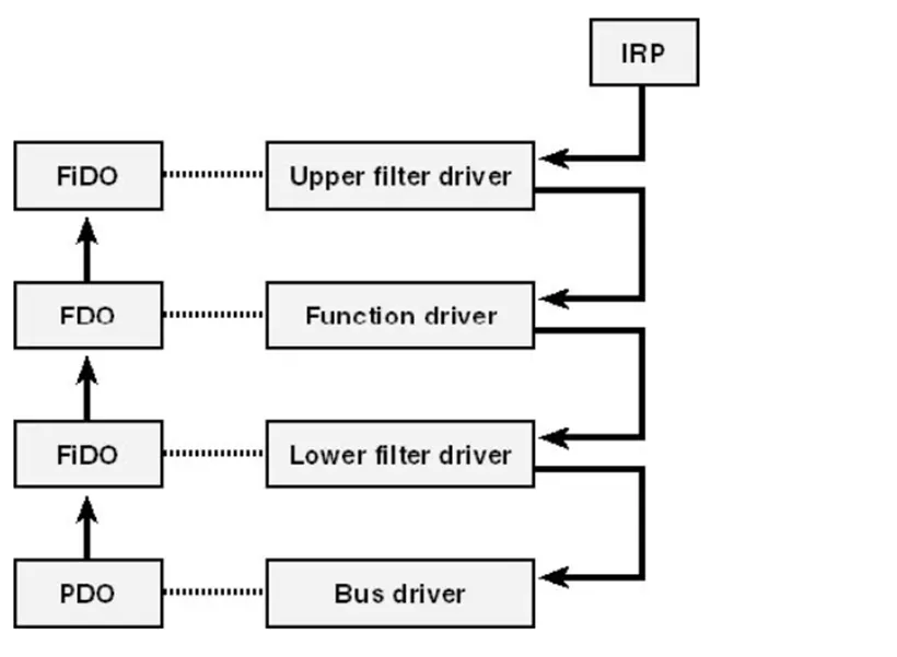
https://flylib.com/books/en/4.168.1.20/2/
IRP
This is how the “_IRP” structure looks like:
1
2
3
4
5
6
7
8
9
10
11
12
13
14
15
16
17
18
19
20
21
22
23
24
25
26
27
28
29
30
31
32
33
34
35
36
37
38
39
40
41
42
43
44
45
46
47
48
49
50
51
52
53
54
55
56
57
58
59
60
61
62
63
64
65
66
67
68
69
70
71
//0xd0 bytes (sizeof)
struct _IRP
{
    SHORT Type;                                                             //0x0
    USHORT Size;                                                            //0x2
    struct _MDL* MdlAddress;                                                //0x8
    ULONG Flags;                                                            //0x10
    union
    {
        struct _IRP* MasterIrp;                                             //0x18
        LONG IrpCount;                                                      //0x18
        VOID* SystemBuffer;                                                 //0x18
    } AssociatedIrp;                                                        //0x18
    struct _LIST_ENTRY ThreadListEntry;                                     //0x20
    struct _IO_STATUS_BLOCK IoStatus;                                       //0x30
    CHAR RequestorMode;                                                     //0x40
    UCHAR PendingReturned;                                                  //0x41
    CHAR StackCount;                                                        //0x42
    CHAR CurrentLocation;                                                   //0x43
    UCHAR Cancel;                                                           //0x44
    UCHAR CancelIrql;                                                       //0x45
    CHAR ApcEnvironment;                                                    //0x46
    UCHAR AllocationFlags;                                                  //0x47
    union
    {
        struct _IO_STATUS_BLOCK* UserIosb;                                  //0x48
        VOID* IoRingContext;                                                //0x48
    };
    struct _KEVENT* UserEvent;                                              //0x50
    union
    {
        struct
        {
            union
            {
                VOID (*UserApcRoutine)(VOID* arg1, struct _IO_STATUS_BLOCK* arg2, ULONG arg3); //0x58
                VOID* IssuingProcess;                                       //0x58
            };
            union
            {
                VOID* UserApcContext;                                       //0x60
                struct _IORING_OBJECT* IoRing;                              //0x60
            };
        } AsynchronousParameters;                                           //0x58
        union _LARGE_INTEGER AllocationSize;                                //0x58
    } Overlay;                                                              //0x58
    VOID (*CancelRoutine)(struct _DEVICE_OBJECT* arg1, struct _IRP* arg2);  //0x68
    VOID* UserBuffer;                                                       //0x70
    union
    {
        struct
        {
            union
            {
                struct _KDEVICE_QUEUE_ENTRY DeviceQueueEntry;               //0x78
                VOID* DriverContext[4];                                     //0x78
            };
            struct _ETHREAD* Thread;                                        //0x98
            CHAR* AuxiliaryBuffer;                                          //0xa0
            struct _LIST_ENTRY ListEntry;                                   //0xa8
            union
            {
                struct _IO_STACK_LOCATION* CurrentStackLocation;            //0xb8
                ULONG PacketType;                                           //0xb8
            };
            struct _FILE_OBJECT* OriginalFileObject;                        //0xc0
        } Overlay;                                                          //0x78
        struct _KAPC Apc;                                                   //0x78
        VOID* CompletionKey;                                                //0x78
    } Tail;                                                                 //0x78
};
PMDL MdlAddress— (Memory Descriptor Layer address). This field is being used to hold an address to a structure called “_MDL” and is a structure that describes a memory that’s being used in a “DIRECT I/O” buffering method. I’ll explain it in depth soon.PVOID SystemBuffer— This field is being used to hold kernel memory address that will hold the memory buffer comes_IO_STATUS_BLOCK IoStatus— A structure that holds 2 main fields:ULONG Information— holds the number of bytes that will be returned in the output back to the requesting client.LONG Status— holds a NTSTATUS value that will tell the status of the IRP.
_IO_STACK_LOCATION CurrentStackLocation— Every “Device Object” layer within the “Device Stack” holds an “_IO_STACK_LOCATION” structure that resides within the “IRP”. The “CurrentStackLocation” holds the current “_IO_STACK_LOCATION” structure based on the current “Device Object” that the IRP is within during the execution. This field isn’t shown in the image above but resides at “_IRP->Tail->Overlay->CurrentStackLocation”.
_IO_STACK_LOCATION
The “_IO_STACK_LOCATION” contains fields that are being used within the IRP that are relevant to the current location within the “Device Stack” that the IRP is in.
1
2
3
4
5
6
7
8
9
10
11
12
13
14
15
16
17
18
19
20
21
22
23
24
25
26
27
28
29
30
31
32
33
34
35
36
37
38
39
40
41
42
43
44
45
46
47
48
49
50
51
52
53
54
55
56
57
58
59
60
61
62
63
64
65
66
67
68
69
70
71
72
73
74
75
76
77
78
79
80
81
82
83
84
85
86
87
88
89
90
91
92
93
94
95
96
97
98
99
100
101
102
103
104
105
106
107
108
109
110
111
112
113
114
115
116
117
118
119
120
121
122
123
124
125
126
127
128
129
130
131
132
133
134
135
136
137
138
139
140
141
142
143
144
145
146
147
148
149
150
151
152
153
154
155
156
157
158
159
160
161
162
163
164
165
166
167
168
169
170
171
172
173
174
175
176
177
178
179
180
181
182
183
184
185
186
187
188
189
190
191
192
193
194
195
196
197
198
199
200
201
202
203
204
205
206
207
208
209
210
211
212
213
214
215
216
217
218
219
220
221
222
223
224
225
226
227
228
229
230
231
232
233
234
235
236
237
238
239
240
241
242
243
244
245
246
247
248
249
250
251
252
253
//0x48 bytes (sizeof)
struct _IO_STACK_LOCATION
{
UCHAR MajorFunction; //0x0
UCHAR MinorFunction; //0x1
UCHAR Flags; //0x2
UCHAR Control; //0x3
union
{
struct
{
struct _IO_SECURITY_CONTEXT* SecurityContext; //0x8
ULONG Options; //0x10
USHORT FileAttributes; //0x18
USHORT ShareAccess; //0x1a
ULONG EaLength; //0x20
} Create; //0x8
struct
{
struct _IO_SECURITY_CONTEXT* SecurityContext; //0x8
ULONG Options; //0x10
USHORT Reserved; //0x18
USHORT ShareAccess; //0x1a
struct _NAMED_PIPE_CREATE_PARAMETERS* Parameters; //0x20
} CreatePipe; //0x8
struct
{
struct _IO_SECURITY_CONTEXT* SecurityContext; //0x8
ULONG Options; //0x10
USHORT Reserved; //0x18
USHORT ShareAccess; //0x1a
struct _MAILSLOT_CREATE_PARAMETERS* Parameters; //0x20
} CreateMailslot; //0x8
struct
{
ULONG Length; //0x8
ULONG Key; //0x10
ULONG Flags; //0x14
union _LARGE_INTEGER ByteOffset; //0x18
} Read; //0x8
struct
{
ULONG Length; //0x8
ULONG Key; //0x10
ULONG Flags; //0x14
union _LARGE_INTEGER ByteOffset; //0x18
} Write; //0x8
struct
{
ULONG Length; //0x8
struct _UNICODE_STRING* FileName; //0x10
enum _FILE_INFORMATION_CLASS FileInformationClass; //0x18
ULONG FileIndex; //0x20
} QueryDirectory; //0x8
struct
{
ULONG Length; //0x8
ULONG CompletionFilter; //0x10
} NotifyDirectory; //0x8
struct
{
ULONG Length; //0x8
ULONG CompletionFilter; //0x10
enum _DIRECTORY_NOTIFY_INFORMATION_CLASS DirectoryNotifyInformationClass; //0x18
} NotifyDirectoryEx; //0x8
struct
{
ULONG Length; //0x8
enum _FILE_INFORMATION_CLASS FileInformationClass; //0x10
} QueryFile; //0x8
struct
{
ULONG Length; //0x8
enum _FILE_INFORMATION_CLASS FileInformationClass; //0x10
struct _FILE_OBJECT* FileObject; //0x18
union
{
struct
{
UCHAR ReplaceIfExists; //0x20
UCHAR AdvanceOnly; //0x21
};
ULONG ClusterCount; //0x20
VOID* DeleteHandle; //0x20
};
} SetFile; //0x8
struct
{
ULONG Length; //0x8
VOID* EaList; //0x10
ULONG EaListLength; //0x18
ULONG EaIndex; //0x20
} QueryEa; //0x8
struct
{
ULONG Length; //0x8
} SetEa; //0x8
struct
{
ULONG Length; //0x8
enum _FSINFOCLASS FsInformationClass; //0x10
} QueryVolume; //0x8
struct
{
ULONG Length; //0x8
enum _FSINFOCLASS FsInformationClass; //0x10
} SetVolume; //0x8
struct
{
ULONG OutputBufferLength; //0x8
ULONG InputBufferLength; //0x10
ULONG FsControlCode; //0x18
VOID* Type3InputBuffer; //0x20
} FileSystemControl; //0x8
struct
{
union _LARGE_INTEGER* Length; //0x8
ULONG Key; //0x10
union _LARGE_INTEGER ByteOffset; //0x18
} LockControl; //0x8
struct
{
ULONG OutputBufferLength; //0x8
ULONG InputBufferLength; //0x10
ULONG IoControlCode; //0x18
VOID* Type3InputBuffer; //0x20
} DeviceIoControl; //0x8
struct
{
ULONG SecurityInformation; //0x8
ULONG Length; //0x10
} QuerySecurity; //0x8
struct
{
ULONG SecurityInformation; //0x8
VOID* SecurityDescriptor; //0x10
} SetSecurity; //0x8
struct
{
struct _VPB* Vpb; //0x8
struct _DEVICE_OBJECT* DeviceObject; //0x10
ULONG OutputBufferLength; //0x18
} MountVolume; //0x8
struct
{
struct _VPB* Vpb; //0x8
struct _DEVICE_OBJECT* DeviceObject; //0x10
} VerifyVolume; //0x8
struct
{
struct _SCSI_REQUEST_BLOCK* Srb; //0x8
} Scsi; //0x8
struct
{
ULONG Length; //0x8
VOID* StartSid; //0x10
struct _FILE_GET_QUOTA_INFORMATION* SidList; //0x18
ULONG SidListLength; //0x20
} QueryQuota; //0x8
struct
{
ULONG Length; //0x8
} SetQuota; //0x8
struct
{
enum _DEVICE_RELATION_TYPE Type; //0x8
} QueryDeviceRelations; //0x8
struct
{
struct _GUID* InterfaceType; //0x8
USHORT Size; //0x10
USHORT Version; //0x12
struct _INTERFACE* Interface; //0x18
VOID* InterfaceSpecificData; //0x20
} QueryInterface; //0x8
struct
{
struct _DEVICE_CAPABILITIES* Capabilities; //0x8
} DeviceCapabilities; //0x8
struct
{
struct _IO_RESOURCE_REQUIREMENTS_LIST* IoResourceRequirementList; //0x8
} FilterResourceRequirements; //0x8
struct
{
ULONG WhichSpace; //0x8
VOID* Buffer; //0x10
ULONG Offset; //0x18
ULONG Length; //0x20
} ReadWriteConfig; //0x8
struct
{
UCHAR Lock; //0x8
} SetLock; //0x8
struct
{
enum BUS_QUERY_ID_TYPE IdType; //0x8
} QueryId; //0x8
struct
{
enum DEVICE_TEXT_TYPE DeviceTextType; //0x8
ULONG LocaleId; //0x10
} QueryDeviceText; //0x8
struct
{
UCHAR InPath; //0x8
UCHAR Reserved[3]; //0x9
enum _DEVICE_USAGE_NOTIFICATION_TYPE Type; //0x10
} UsageNotification; //0x8
struct
{
enum _SYSTEM_POWER_STATE PowerState; //0x8
} WaitWake; //0x8
struct
{
struct _POWER_SEQUENCE* PowerSequence; //0x8
} PowerSequence; //0x8
struct
{
union
{
ULONG SystemContext; //0x8
struct _SYSTEM_POWER_STATE_CONTEXT SystemPowerStateContext; //0x8
};
enum _POWER_STATE_TYPE Type; //0x10
union _POWER_STATE State; //0x18
enum POWER_ACTION ShutdownType; //0x20
} Power; //0x8
struct
{
struct _CM_RESOURCE_LIST* AllocatedResources; //0x8
struct _CM_RESOURCE_LIST* AllocatedResourcesTranslated; //0x10
} StartDevice; //0x8
struct
{
ULONGLONG ProviderId; //0x8
VOID* DataPath; //0x10
ULONG BufferSize; //0x18
VOID* Buffer; //0x20
} WMI; //0x8
struct
{
VOID* Argument1; //0x8
VOID* Argument2; //0x10
VOID* Argument3; //0x18
VOID* Argument4; //0x20
} Others; //0x8
} Parameters; //0x8
struct _DEVICE_OBJECT* DeviceObject; //0x28
struct _FILE_OBJECT* FileObject; //0x30
LONG (*CompletionRoutine)(struct _DEVICE_OBJECT* arg1, struct _IRP* arg2, VOID* arg3); //0x38
VOID* Context; //0x40
};
Let’s go over some important fields within the “_IO_STACK_LOCATION” structure:
UCHAR MajorFunction- holds the “MajorFunction” value that the “IRP” requests._DEVICE_OBJECT * DeviceObject- holds a pointer to the current layer of the “Device Object” structure address within the “Device Stack”._FILE_OBJECT * FileObject- holds a pointer to the “_FILE_OBJECT” pointer that represents the current interaction with the device and represents an open instance of a device.LONG *CompletionRoutine- Every layer within the “Device Stack” has the ability to register a functionality called “Completion Routine”. The “Completion Routine” is a callback routine that’s being automatically executed after the IRP request has been completed in an order based on the “Device Stack” (The lowest layer that has the callback routine will be executed first, then the layer above it, and then the layer above it, etc…).Union Parameters- This “union” is very important and it holds an additional useful information related to the buffer based on the “MajorFunction” value. For example, if the “MajorFunction” is for a “Write” operation, then the “union” will hold the structure of “Write” and will hold information such as “Length”, “Key”, “Flags” etc.. Another example is if the request is “Device IO Control” request. Than, the structure that will be setted in the “union” is “DeviceIoControl” structure, which hold fields such as “OutputBufferLength”, “InputBufferLength”, “IoControlCode” which is used to receive the IOCTL given from the client and more fields..
Continuing in the _IRP fields:
CHAR StackCount- This value holds the number of the devices within the “Device Stack” that the IRP is expected to go through. This is also the number of “_IO_STACK_LOCATION”’s structures that the IRP holds within for every device layer within the “Device Stack”PRKEVENT UserEvent- An “Event Object” that’s being transferred by the client and can be used for a synchronization/notification object. This can be useful for the client to get a notification for certain events that occur during the execution of the IRP.VOID * CancelRoutine- A pointer to a cancellation routine that will be executed automatically if the IRP is being cancelled during it’s execution.
Now, let’s talk about in which ways a buffer of data is being passed from the client to the driver itself in the IRP. Mainly, there are 2 main buffering methods:
Buffered I/O- This technique is a buffering technique that performs an allocation of a non-paged kernel memory. Then, the buffer of the request is being copied into that memory space and being used during the IRP’s execution. The pointer to the non-paged kernel memory that stores the user buffer resides in the “_IRP->AssociatedIrp->SystemBuffer”.1 2
If the operation is only a read operation that doesn’t involve transferring buffer from the client to the buffer, then the allocated **“SystemBuffer”** will only be used to hold the output data and return it to the client. If the request is a write operation, then the input buffer from the client will be copied into the allocated **“SystemBuffer”** and will be used during execution. For a case where there is an output buffer that should be returned back to the client, it will return in a copy operation that will run as **“Special Kernel APC”** at **IRQL 1 (APC_LEVEL)** and the output buffer will be copied back to the client and the allocated kernel memory buffer will be freed.`Direct I/O - This technique involves direct memory mapping, which maps a view of the buffer in kernel space and the operations of the IRP will be reflected directly on the physical memory of the client buffer. The technique starts by checking if the pages where the buffer resides are within RAM and not paged-out into “Page File”.
Then, these pages are being locked in memory using the function “MmProbeAndLockPages()” which makes sure that these pages can’t be paged-out or freed while they are being used. The buffer’s pages are being described through a structure called “_MDL” (Memory Descriptor Layer) and are being used during the direct mapping of the client buffer in kernel memory.
The “_MDL” structure:
1
2
3
4
5
6
7
8
9
10
11
12
//0x30 bytes (sizeof)
struct _MDL
{
    struct _MDL* Next;                                                      //0x0
    SHORT Size;                                                             //0x8
    SHORT MdlFlags;                                                         //0xa
    struct _EPROCESS* Process;                                              //0x10
    VOID* MappedSystemVa;                                                   //0x18
    VOID* StartVa;                                                          //0x20
    ULONG ByteCount;                                                        //0x28
    ULONG ByteOffset;                                                       //0x2c
};
struct _MDL * Next— holds the next entry in a linked list of chained “_MDL” structures that are being used in case where the buffer isn’t contigious in physical memory.“VOID *StartVa”— The virtual address of the page that’s part of the client buffer.VOID *MappedSystemVa— holds the view kernel address of the mapped buffer in kernel memory. This is the address used in kernel memory during the execution of the IRP.SHORT Size- holds the size of the current “_MDL” structure.ULONG ByteCount- The size in bytes of the buffer described by the “_MDL” structure.ULONG ByteOffset- The offset in bytes of the buffer from the beginning of the data described by the “_MDL”. This is being used to describe a sub-region of a larger buffer.struct _EPROCESS * Process- holds the “_EPROCSS” structure address of the process that owns the memory described by the “_MDL” structure.
After being the MDLs required to interact with the memory page that holds the buffer, the function “MmGetSystemAddressForMdlSafe()” is being used by the driver to receive a pointer to the mapped kernel space pages. Any modifications to the pages will be reflected on the client buffer memory. When finishing execution, the “_MDL” structures are being released, the second mapping to kernel space is being released, and the locked memory pages are also being released, so they can be freed or paged-out if needed.
There are multiple ways to tell the buffering method to use:
Through flags in the “_DEVICE_OBJECT” — There are 2 flags that can be setted in the device object and will tell the device in which way to accept the buffering method — “DO_BUFFERED_IO” which tells the buffer to accept buffers only using the “Buffered I/O” method, and the second way is “DO_DIRECT_IO”, which tells the “Device Object” that the buffer that is going to given to it will be transferred in a “Direct I/O” method.
If any of the flags above are not set, it is possible to define the buffering method when declaring an IOCTL (which we’ll see later how). The macro “METHOD_BUFFERED” tells that the buffer that will be transferred into the IOCTL will be transferred in a “Buffered I/O” method. The second macro is a “METHOD_DIRECT” which tells that the IOCTL will receive the buffer in a “Direct I/O” method, and the 3rd macro is “METHOD_NEITHER” which tells that the IOCTL is going to directly use the user buffer, without any “System Buffer” or an “MDL”, which is very unsafe and unrecommended.
After having this understanding, let’s dive into the practical aspect and create a basic driver and a client that interacts with the driver, and see how we can debug it in WinDbg.
For starting a driver project in Visual Studio, we’ll need to download WDK (Windows Driver Kit): https://learn.microsoft.com/en-us/windows-hardware/drivers/download-the-wdk
Driver Development - Demo
After downloading and installing it in Visual Studio, we’ll open an “Empty WDM Driver”, and create a “.cpp” file which will hold the code for the driver. Now, we’ll include “ntddk.h” which holds the “Driver Development Kit” set of kernel functions within it, and starts to initialize the “DriverEntry()” function, which is the entry function of every driver:
1
2
3
4
extern "C"
NTSTATUS DriverEntry(PDRIVER_OBJECT DriverObject, PUNICODE_STRING RegistryPath)
{
}
The “DriverEntry()” function returns a NTSTATUS value, and to avoid name mangling in C++, we’ll need to tell the compiler to treat it as a “C” function where there will be no name mangling by declaring an extern “C” on the function.
The DriverEntry() also receives 2 arguments:
PDRIVER_OBJECT DriverObject— The base address pointer to the “DRIVER_OBJECT” structure, which represents the driver in kernel space.PUNICODE_STRING RegistryPath— Drivers that are registered holds configuration within the registry that will help the Operating System to load the driver at initialization.
The registry path is at: HKEY_LOCAL_MACHINE\SYSTEM\CurrentControlSet\Services\<DriverName> and it holds the following arguments:
ImagePath: Specifies the path to the driver’s executable.Type: Indicates the type of service (e.g., kernel-mode driver, file system driver).Start: Defines the startup type (e.g., boot, system, automatic, manual, disabled).ErrorControl: Determines the error severity if the driver fails to load.Parameters: A subkey where additional driver-specific parameters can be stored.
Now, the next thing the driver needs to do is to initialize the “Device Object” it will be controlling and set a symlink to it. This can be done using the following kernel API functions:
IoCreateDevice() — An I/O manager function that creates a device object with a “_DEVICE_OBJECT” structure which represents the device in kernel memory.
1
2
3
4
5
6
7
8
9
NTSTATUS IoCreateDevice(
  [in]           PDRIVER_OBJECT  DriverObject,
  [in]           ULONG           DeviceExtensionSize,
  [in, optional] PUNICODE_STRING DeviceName,
  [in]           DEVICE_TYPE     DeviceType,
  [in]           ULONG           DeviceCharacteristics,
  [in]           BOOLEAN         Exclusive,
  [out]          PDEVICE_OBJECT  *DeviceObject
);
IoCreateSymbolicLink() — An I/O Manager function that creates a symbolic link that gives an easier way to get a handle to the device.
1
2
3
4
NTSTATUS IoCreateSymbolicLink(
  [in] PUNICODE_STRING SymbolicLinkName,
  [in] PUNICODE_STRING DeviceName
);
Here is the basic implementation of creating a “Device Object” and a symlink to the device:
1
2
3
4
5
6
7
8
9
10
11
12
13
14
15
16
17
18
19
20
21
22
23
24
25
26
27
28
29
extern "C"
NTSTATUS DriverEntry(PDRIVER_OBJECT DriverObject, PUNICODE_STRING RegistryPath)
{
	UNREFERENCED_PARAMETER(RegistryPath);

	NTSTATUS status = STATUS_SUCCESS;
	UNICODE_STRING DeviceName = RTL_CONSTANT_STRING(L"\\Device\\DriverDemoDevice");
	UNICODE_STRING DeviceSymLink = RTL_CONSTANT_STRING(L"\\??\\DriverDemoDevice");
	PDEVICE_OBJECT DevObj;

	status = IoCreateDevice(DriverObject, 0, &DeviceName, FILE_DEVICE_UNKNOWN, 0, FALSE, &DevObj);
	if(!NT_SUCCESS(status))
	{
		KdPrint(("[-] DriverDemo::DriverEntry: Couldn't create the device (0x%x)\n", status));
		return status;
	}

	KdPrint(("[+] DriverDemo::DriverEntry: Device %wZ created successfully!\n", &DeviceName));

	status = IoCreateSymbolicLink(&DeviceSymLink, &DeviceName);
	if(!NT_SUCCESS(status))
	{
		KdPrint(("[-] DriverDemo::DriverEntry: Couldn't create a Symbolic Link to the device (0x%x)\n", status));
		IoDeleteDevice(DevObj);		// Deletes the device and returns if symlink creation wasn't successful
		return status;
	}

	return status;
}
The “IoDeleteDevice()” function deletes the device in case there was an error creating a symbolic link.
Now after creating the device and a symlink to the device, we’ll need to the declare the “Dispatch Routines” (The functions that handles the functionality of the driver and are stored within the “MajorFunctions” array of the driver). Every “Dispatch Routine” accepts a pointer to the “_DEVICE_OBJECT” structure of the device and a pointer to the “_IRP” structure.
Let’s start by declaring these functions and an unload routine and we’ll implement them after:
1
2
3
4
5
NTSTATUS CreateClose(PDEVICE_OBJECT DeviceObject, PIRP irp);

NTSTATUS DeviceControlHandler(PDEVICE_OBJECT DeviceObject, PIRP irp);

VOID UnloadRoutine(PDRIVER_OBJECT DriverObject);
Now we’ll attach them to the “MajorFunction” array within the “_DRIVER_OBJECT” structure:
1
2
3
4
5
6
DriverObject->MajorFunction[IRP_MJ_CREATE] = CreateClose;
DriverObject->MajorFunction[IRP_MJ_CLOSE] = CreateClose;
DriverObject->MajorFunction[IRP_MJ_DEVICE_CONTROL] = DeviceControlHandler;
DriverObject->DriverUnload = UnloadRoutine;

return status;
Now we’ll start by implementing the “CreateClose()” function, which will be invoked when the client uses the “CreateFile()” and “CloseFile()” functions on the device object.
Here is the implementation of the “CreateClose()” function:
1
2
3
4
5
6
7
8
NTSTATUS CreateClose(PDEVICE_OBJECT DeviceObject, PIRP irp)
{
	UNREFERENCED_PARAMETER(DeviceObject);
	irp->IoStatus.Status = STATUS_SUCCESS;
	irp->IoStatus.Information = 0;
	IoCompleteRequest(irp, IO_NO_INCREMENT);
	return STATUS_SUCCESS;
}
Since we don’t have anything special to do when the “CreateFile()” function is being invoked, we’ll just complete the request with “IoCompleteRequest()”.
Every “Dispatch Routine” has to update the “IoStatus” structure within the “IRP” based on the status of execution at the end and provide the number of bytes that will be returned to the output buffer after execution.
Now, let’s implement the IOCTL handler of the driver. I will show the implementation of the handler and I’ll go over it. To define an IOCTL, we’ll need to use a macro called “CTL_CODE()” which calculates an IOCTL value. It calculates the IOCTL code using 4 arguments:
1
void CTL_CODE(DeviceType, Function, Method, Access)
DeviceType— a hex value that should be 0x8001 or above (according to microsoft’s documentation) and gives a device some sort of an ID number.Function— another hex value that needs to be 0x801 and above and serves as an ID for the function.Method— tells which buffering method the IOCTL is going to implement, there are 3 methods:METHOD_BUFFERRED— Input buffer & output buffer are going to be both transferred through “Buffered I/O” method.METHOD_OUT_DIRECT— Input buffer is going to be transferred through “Buffered I/O” and output buffer will be transferred through “Direct I/O” method.METHOD_NEITHER— The driver is going to directly interact with the buffer without the driver’s providing any “System Buffers” or “MDLs”. This is a dangerous method that can potentially expose the drivers to vulnerabilities.
ACCESS— Access check values, we’re going to set this setting to “FILE_ANY_ACCESS”.
With that understanding, we’ll create a new header file (“.h” file) and declare the IOCTLs in the following way:
#pragma once

#define DriverDemoType 0x8005

#define IOCTL_BUFFERED_METHOD CTL_CODE(DriverDemoType, 0x801, METHOD_BUFFERED, FILE_ANY_ACCESS)
#define IOCTL_DIRECT_METHOD CTL_CODE(DriverDemoType, 0x802, METHOD_OUT_DIRECT, FILE_ANY_ACCESS)
#define IOCTL_METHOD_NEITHER CTL_CODE(DriverDemoType, 0x803, METHOD_NEITHER, FILE_ANY_ACCESS)
I declared 3 IOCTLs to demonstrate each of the buffering methods used by drivers. The driver is going to receive an input buffer that holds a size in bytes. Then, the driver is going to use this value and allocate a “Paged Pool” memory based on given value that resides in the input buffer from the client code. After allocating the memory, the output buffer will include a success message that will be returned to the client at the end of the execution.
With that understanding, let’s see the first lines in the “DeviceControlHandler()” dispatch routine:
1
2
3
4
5
6
7
8
9
10
11
NTSTATUS DeviceControlHandler(PDEVICE_OBJECT DeviceObject, PIRP irp)
{
	UNREFERENCED_PARAMETER(DeviceObject);
	_IO_STACK_LOCATION* StackLocation = IoGetCurrentIrpStackLocation(irp);
	NTSTATUS status = STATUS_SUCCESS;
	char message[512] = {0};
	ULONG information = 0;
	ULONG InputBufferLength = StackLocation->Parameters.DeviceIoControl.InputBufferLength;
	ULONG OutputBufferLength = StackLocation->Parameters.DeviceIoControl.OutputBufferLength;
    ...
}
Because the “DeviceObject” argument isn’t going to be directly used during the execution of the function, we’ll use the UNREFERENCED_PARAMETER() macro so that the linker will set a value to it. If we won’t do that we’ll receive a compiling warning treated as error.
After that, we declared multiple variables:
StackLocation— A variable that holds the current_IO_STACK_LOCATIONstructure. This structure is going to be used during the execution to receive information about the IRP request, such as the IOCTL code received from the client, Input Buffer length, Output Buffer length, etc…message- A variable that will hold the message that will be returned from the driver to the client in the output buffer.information- A variable that will be used to fill the “IoStatus->information” field, which will hold the number of bytes of the returned output buffer.InputBufferLength&OutputBufferLength- Variables are getting their information from the current “Stack Location” and gets the given size of the input buffer and output buffer supplied by the requesting client.
Next, to handle each IOCTL based on it’s code, the given IOCTL code is going to be handled through a “switch()” statement that holds a set of cases, each case is an IOCTL value we defined in the header file.
We’ll start with the implementation of the first IOCTL, which is “IOCTL_BUFFERED_METHOD”:
1
2
3
4
5
6
7
8
9
10
11
12
13
14
15
16
17
18
19
20
21
22
23
24
25
26
27
28
29
30
	switch (StackLocation->Parameters.DeviceIoControl.IoControlCode)
	{
	case IOCTL_BUFFERED_METHOD:
	{
		/*
		This IOCTL demonstrates the Buffered I/O buffering method
		The IOCTL will receive an input buffer that will hold value which is a number of bytes of kernel paged-pool memory that will
		be allocated through ExAllocatePool2()
		*/
		KdPrint(("[+] IOCTL_BUFFERED_METHOD has been invoked!!\n"));
		auto InputBuffer = (ULONG*)irp->AssociatedIrp.SystemBuffer; // Buffered I/O input Buffer that holds the number of bytes to allocate
		auto OutputBuffer = (CHAR*)irp->AssociatedIrp.SystemBuffer; // Buffered I/O output buffer that will return a sucess message after execution.
		if (OutputBufferLength <= 0 || InputBufferLength < sizeof(ULONG))
		{
			status = STATUS_INSUFFICIENT_RESOURCES;
			break;
		}

		ULONG NumberOfBytes = (ULONG)*InputBuffer;
;		KdPrint(("[*] DemoDriver::DeviceControlHandler: Number of bytes that's going to be allocated: %d\n", NumberOfBytes));

		AllocatedPoolMemoryBuffered = ExAllocatePool2(POOL_FLAG_PAGED, NumberOfBytes, 'omeD');
		KdPrint(("[+] DemoDriver::DeviceControlHandler: Memory was successfully allocated at address: 0x%p\n", AllocatedPoolMemoryBuffered));
		sprintf(message, "IOCTL IOCTL_BUFFERED_METHOD (0x%x) was executed successfully!! allocated %d bytes at address: 0x%p\n", status, NumberOfBytes, AllocatedPoolMemoryBuffered);
		information = (ULONG)strlen(message) + 1;
		RtlCopyMemory(OutputBuffer, message, information);
		break;
	}
    ...
    }
The given IOCTL code is received from StackLocation>Parameters.DeviceIoControl.IoControlCode.
The handler for “IOCTL_BUFFERED_METHOD” starts with a “KdPrint(())” macro that is a wrapper around the “DbgPrint()” function that prints information to a debugger (such as “dbgview.exe”). The buffers for input and output are both received and returned from the Irp->AssociatedIrp.SystemBuffer field (since we setted METHOD_BUFFERED macro value within the CTL_CODE() macro that created the IOCTL).
Next, we perform a sanity check that verifies that the given buffers from the client are valid in size, and if not, a “STATUS_INSUFFICIENT_RESOURCES” will be returned in the “IoStatus” structure of the “IRP”.
Next, the input buffer which holds the size in bytes to allocate, is being transferred into a new variable called “ULONG NumberOfBytes”. Next, the paged-pool memory allocation is being performed using the “ExAllocatePool2()” function:
1
2
3
4
5
DECLSPEC_RESTRICT PVOID ExAllocatePool2(
  POOL_FLAGS Flags,
  SIZE_T     NumberOfBytes,
  ULONG      Tag
);
POOL_FLAGS Flags- A flag value which add attributes to the allocation, in our case we used the “POOL_FLAG_PAGED” to tell that the memory needs to be allocated as a “Paged Pool Memory”.SIZE_T NumberOfBytes- Number of bytes, which we received from the buffer.ULONG Tag- A “tag” is a DWORD (4 characters) value that is used in order to describe and classify the purpose of the allocated memory. In our case, we use the ‘Demo’ tag in a little endian format (‘omeD’). The “AllocatedPoolMemoryBuffered” variable is a global variable that will need to be freed during the execution of the “Unload Routine” which we’ll implement at the end.
After allocating, we print a message to “dbgview” (using the “KdPrint(())” macro) and fill the output buffer with a message that will be returned to the client, and setting the “Information” field in the “IoStatus” to hold the size of the output buffer message, which is number of bytes + null terminator byte.
The next IOCTL is the “IOCTL_DIRECT_METHOD” that is used to demonstrate the implementation of “Direct I/O” buffering method:
1
2
3
4
5
6
7
8
9
10
11
12
13
14
15
16
17
18
19
20
21
	case IOCTL_DIRECT_METHOD:
	{
		KdPrint(("[+] IOCTL_DIRECT_METHOD has been invoked!!\n"));
		if (OutputBufferLength <= 0 || InputBufferLength < sizeof(ULONG)) {
			status = STATUS_INSUFFICIENT_RESOURCES;
			break;
		}
		auto InputBuffer = (ULONG*)irp->AssociatedIrp.SystemBuffer;	//Input buffer is received in Buffered I/O method.
		auto OutputBuffer = MmGetSystemAddressForMdlSafe(irp->MdlAddress, NormalPagePriority); //output buffer is in direct memory mapping through _MDL structure

		ULONG NumberOfBytes = (ULONG)*InputBuffer;
		KdPrint(("[*] DemoDriver::DeviceControlHandler: Number of bytes that's going to be allocated: %d\n", NumberOfBytes));

		AllocatedPoolMemoryDirect = ExAllocatePool2(POOL_FLAG_PAGED, NumberOfBytes, 'omeD'); // tag is 'Demo' reversed because of endianness
		KdPrint(("[+] DemoDriver::DeviceControlHandler: Memory was successfully allocated at address: 0x%p\n", AllocatedPoolMemoryDirect));

		sprintf(message, "IOCTL IOCTL_DIRECT_METHOD (0x%x) was executed successfully!! allocated %d bytes at address: 0x%p\n", status, NumberOfBytes, AllocatedPoolMemoryDirect);
		information = (ULONG)strlen(message) + 1;
		RtlCopyMemory(OutputBuffer, message, information);
		break;
	}
The implementation is pretty similar to the “IOCTL_BUFFERED_METHOD” but the main difference is that a view of the “Output Buffer” is being mapped into kernel space and the modifications in the buffer are being reflected directly into the client. The output buffer view address is being retrieved using the “MmGetSystemAddressForMdlSafe()” (The input buffer is always being received in a Buffered I/O method in IOCTLs). Another thing to note is that here, the “AllocatePoolMemoryDirect” variable is also a global variable that will be freed at the execution of “Unload Routine”.
The last IOCTL is the IOCTL_METHOD_NEITHER, which is used to demonstrate the “METHOD_NEITHER” method:
1
2
3
4
5
6
7
8
9
10
11
12
13
14
15
16
17
18
19
20
21
22
23
24
25
26
27
28
29
30
31
32
33
34
35
36
37
38
39
	case IOCTL_METHOD_NEITHER:
	{
		KdPrint(("[+] IOCTL_METHOD_NEITHER has been invoked!!\n"));
		auto InputBuffer = (ULONG*)StackLocation->Parameters.DeviceIoControl.Type3InputBuffer;
		if (InputBuffer == NULL || InputBufferLength == 0)
		{
			status = STATUS_INVALID_PARAMETER;
			KdPrint(("[-] DemoDriver::DeviceControlHandler: Invalid METHOD_NEITHER parameter received\n"));
			/*;
			sprintf(message, "[-] DemoDriver::DeviceControlHandler: Invalid METHOD_NEITHER parameter received\n");
			information = (ULONG)strlen(message) + 1;
			RtlCopyMemory()*/
			break;
		}
		__try {
			//ProbeForRead() checks if the given address is a valid user-mode address and can be used for reading
			ProbeForRead(InputBuffer, InputBufferLength, sizeof(ULONG));

			ULONG NumberOfBytes = *((PULONG)InputBuffer);
			KdPrint(("[*] DemoDriver::DeviceControlHandler: Number of bytes that's going to be allocated: %d\n", NumberOfBytes));

			AllocatedPoolMemoryNeither = ExAllocatePool2(POOL_FLAG_PAGED, NumberOfBytes, 'omeD');
			KdPrint(("[+] DemoDriver::DeviceControlHandler: Memory was successfully allocated at address: 0x%p\n", AllocatedPoolMemoryNeither));

			sprintf(message, "IOCTL_METHOD_NEITHER (0x%x) was executed successfully!! allocated %d bytes at address: 0x%p", status, NumberOfBytes, AllocatedPoolMemoryNeither);
			information = (ULONG)strlen(message) + 1;
			RtlCopyMemory(InputBuffer, message, information);
			break;
		}
		__except (EXCEPTION_EXECUTE_HANDLER)
		{
			status = STATUS_INVALID_PARAMETER; // Throw an NTSTATUS code
			break;
		}
	}
	default:
		status = STATUS_INVALID_DEVICE_REQUEST;
		break;
	}
The “IOCTL_METHOD_NEITHER” IOCTL handler starts by a simple validation of the given input buffer. Then, the function continues validation by executing a ProbeForRead(), which validates if the given address resides in a valid User-Mode address and can be use for reading. Next, a “__try/__except” block is being executed, which performs the paged pool memory, which is similar to what’s done in the 2 preivous IOCTL handlers.
After the “switch” statement, the “IoStatus” structure within the “IRP” structure is being filled with the needed data. After that, a IoCompleteRequest() is being called to complete the IRP request:
1
2
3
4
5
	irp->IoStatus.Status = status;
	irp->IoStatus.Information = information;
	IoCompleteRequest(irp, IO_NO_INCREMENT);

	return status;
Now, the last thing we need to implement is the “Unload Routine” that’s being invoked at driver unload:
1
2
3
4
5
6
7
8
9
10
11
12
13
14
15
16
17
18
19
20
21
22
23
24
25
26
27
28
29
VOID UnloadRoutine(PDRIVER_OBJECT DriverObject)
{
	UNICODE_STRING DeviceSymLink = RTL_CONSTANT_STRING(L"\\??\\DriverDemoDevice");
	PDEVICE_OBJECT DevObj = DriverObject->DeviceObject;

	IoDeleteDevice(DevObj);
	KdPrint(("[+] DriverDemo::UnloadRoutine: Device deleted successfully!!\n"));

	IoDeleteSymbolicLink(&DeviceSymLink);
	KdPrint(("[+] DriverDemo::UnloadRoutine: Symlink deleted successfully!!\n"));

	if (AllocatedPoolMemoryDirect)
	{
		KdPrint(("[+] DriverDemo::UnloadRoutine: Allocated Pool memory from Direct at address 0x%p was freed successfully!\n", AllocatedPoolMemoryDirect));
		ExFreePool(AllocatedPoolMemoryDirect);
	}
	if (AllocatedPoolMemoryBuffered)
	{
		ExFreePool(AllocatedPoolMemoryBuffered);
		KdPrint(("[+] DriverDemo::UnloadRoutine: Allocated Pool memory from Buffered at address 0x%p was freed successfully!\n", AllocatedPoolMemoryBuffered));
	}

	if (AllocatedPoolMemoryNeither)
	{
		ExFreePool(AllocatedPoolMemoryNeither);
		KdPrint(("[+] DriverDemo::UnloadRoutine: Allocated Pool memory from Neither at address 0x%p was freed successfully!\n", AllocatedPoolMemoryNeither));
	}
	KdPrint(("[+] DriverDemo::UnloadRoutine: Unload routine was completed successfully!\n"));
}
The “Unload Routine” deletes the device object created at “DriverEntry()” and deletes the Symbolic Link created. After that, it checks if there are allocated buffers that were allocated and needs to be freed, and if so, frees them using the “ExFreePool()”.
Now, let’s create the client code that invokes the requests from user mode:
1
2
3
4
5
6
7
8
9
10
11
12
13
14
15
16
17
18
19
20
21
22
23
24
25
26
27
28
29
30
31
32
33
34
35
36
37
38
39
40
41
42
43
44
45
46
47
48
49
50
51
52
53
54
55
56
57
58
59
60
61
62
63
64
65
66
67
68
#include <stdio.h>
#include <stdlib.h>
#include <Windows.h>
#include "ClientDriverDemoHeader.h"

int main(int s, const char* argv[]) {

    HANDLE hDevice = CreateFile(LR"(\\.\DriverDemoDevice)", GENERIC_READ | GENERIC_WRITE, 0, nullptr, OPEN_EXISTING, 0, nullptr);
    if (hDevice == INVALID_HANDLE_VALUE) {
        printf("Handle to the device couldn't be created: %u\n", GetLastError());
        return -1;
    }

    ULONG InputBuffer = 0x1000;
    CHAR message[512];
    DWORD BytesReturned;
    int result = DeviceIoControl(hDevice,      // Handle to Device Object
        IOCTL_BUFFERED_METHOD,                 // IOCTL
        &InputBuffer,                          // InputBuffer
        sizeof(InputBuffer),                   // Size of InputBuffer
        message,                               // OutputBuffer
        512,                                   // size of OutputBuffer
        &BytesReturned,                        // Bytes Returned
        nullptr);

    if (result)
        printf("\n IOCTL_BUFFERED_METHOD:\nData Received from driver: \n%s\n", message);
    else
        printf("\n IOCTL_BUFFERED_METHOD Problem with executing IOCTL... (%u)\n", GetLastError());

    getchar();
    result = DeviceIoControl(hDevice,      // Handle to Device Object
        IOCTL_DIRECT_METHOD,               // IOCTL
        &InputBuffer,                      // InputBuffer
        sizeof(InputBuffer),               // Size of InputBuffer
        message,                           // OutputBuffer
        512,                               // size of OutputBuffer
        &BytesReturned,                    // Bytes Returned to OutputBuffer
        nullptr);

    if (result)
        printf("\n IOCTL_DIRECT_METHOD: Data Received from driver: %s\n", message);
    else
        printf("\n IOCTL_DIRECT_METHOD Problem with executing IOCTL... (%u)\n", GetLastError());
    getchar();

    PVOID Buffer = VirtualAlloc(nullptr, 0x1000, MEM_COMMIT | MEM_RESERVE, PAGE_READWRITE);
    ULONG Size = 0x1000;
    RtlCopyMemory(Buffer, &Size, sizeof(ULONG));
    result = DeviceIoControl(hDevice,      // Handle to Device Object
        IOCTL_METHOD_NEITHER,              // IOCTL
        Buffer,                            // InputBuffer
        sizeof(Buffer),                    // Size of InputBuffer
        Buffer,                            // OutputBuffer
        sizeof(Buffer),                    // size of OutputBuffer
        &BytesReturned,                    // Bytes Returned to OutputBuffer
        nullptr);

    if (result)
        printf("\n IOCTL_METHOD_NEITHER: Data Received from driver: %s\n", (char*)Buffer);
    else
        printf("\n IOCTL_METHOD_NEITHER Problem with executing IOCTL... (%u)\n", GetLastError());

    getchar();
    CloseHandle(hDevice);
    VirtualFree(Buffer, sizeof(Buffer), MEM_RELEASE);
    return 0;
}
The “main()” function starts by getting a handle to device using the “CreateFile()” API function. After that, to invoke a call to an IOCTL of a driver, a call to “DeviceIoControl()” function is needed:
1
2
3
4
5
6
7
8
9
10
BOOL DeviceIoControl(
  [in]                HANDLE       hDevice,
  [in]                DWORD        dwIoControlCode,
  [in, optional]      LPVOID       lpInBuffer,
  [in]                DWORD        nInBufferSize,
  [out, optional]     LPVOID       lpOutBuffer,
  [in]                DWORD        nOutBufferSize,
  [out, optional]     LPDWORD      lpBytesReturned,
  [in, out, optional] LPOVERLAPPED lpOverlapped
);
HANDLE hDevice- A handle to the device object.DWORD dwIoControlCode- A DWORD value ofIO Control Codethat we want to invoke.LPVOID lpInBuffer**- A pointer to the input buffer that will be passed to the IOCTL.DWORD nInBufferSize- Number of bytes of the input buffer.LPVOID lpOutBuffer- A pointer to the output buffer that will be passed to the IOCTL.DWORD nOutBufferSize- Number of bytes of the output buffer.LPDWORD lpBytesReturned- Number of bytes returned from the IOCTL’s output buffer.
In the client code, we have 3 “DeviceIoControl()” requests, one for the “IOCTL_BUFFERED_METHOD” for demonstrating the “Buffered I/O” method, the second for “IOCTL_DIRECT_METHOD” for demonstrating the “Direct I/O” method and the third one is for “IOCTL_METHOD_NEITHER”.
Both of the first “DeviceIoControl()” requests have the same input buffer and output buffer that are being passed to the IOCTLs. The input buffer holds the size of the non-paged pool memory to allocate, and the output buffer is a buffer of “message” that has the size of 512 bytes (chars).
After each “DeviceIoControl()” request there is a printf() call that prints the data returned from the driver.
Now, after understanding how both the driver code and the client code works, it’s time to demonstrate the driver’s functionality and see some commands that can be used in WinDbg.
For that we’ll use a windows 10 VM that has kernel debugging functionaliy enabled. To enable remote kernel debugging, you can follow this article: https://scorpiosoftware.net/2023/03/07/levels-of-kernel-debugging/
We’ll also need to get into “Test Mode” which allow us to run unsigned drivers in a system. To enable “Test Mode”, you can follow this article: https://learn.microsoft.com/en-us/windows-hardware/drivers/install/the-testsigning-boot-configuration-option
If “Secure Boot” is enabled and prevents you from enabling “Test Mode”, use this article to disable “Secure Boot” on the VM: https://learn.microsoft.com/en-us/windows-hardware/manufacture/desktop/disabling-secure-boot?view=windows-11
With that out of the way, we can now open WinDbg and initiate a remote kernel debugging on the target machine:
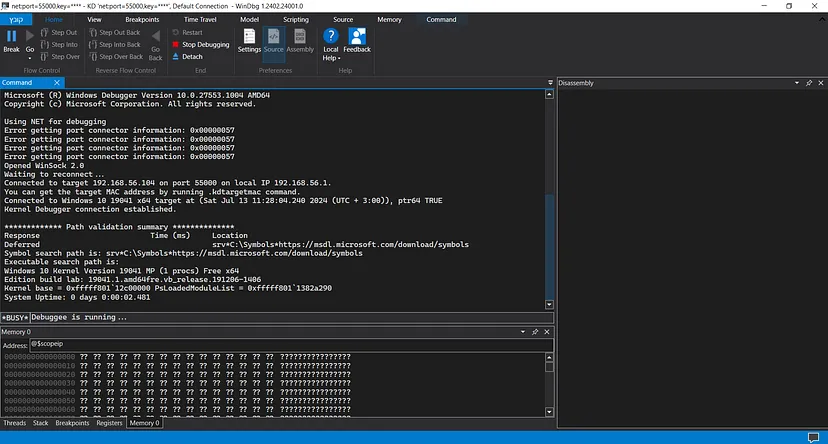
Let’s transfer both the driver and the client executable into the remote machine.
To load the driver, we’ll need to open “cmd.exe” with administrator privileges and create a service that will load the driver into the system. For that we’ll execute the following command:
sc create DemoDriver type= kernel binpath=C:\Path\to\Driver.sys
Now that the service that should load the driver is created, let’s open “dbgview.exe”, which will allow us to view the messages we printed using the “KdPrint(())” macro:
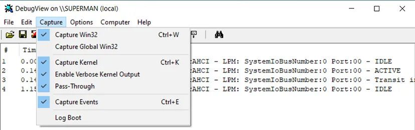
To view full kernel verbosity, we need to check both “Capture Kernel” and “Enable Verbose Kernel Output”.
Now, let’s execute the service we created, which will cause the drvier to be loaded into system space:
sc start DemoDriver
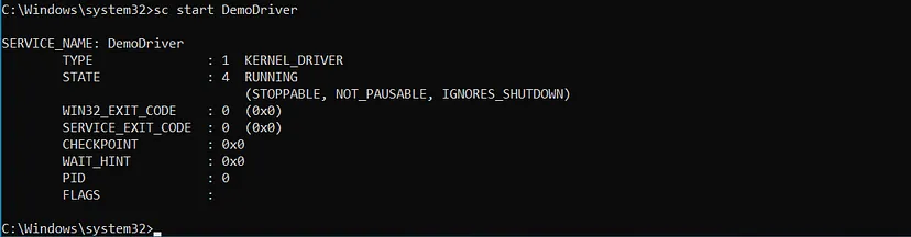
Viewing “dbgview.exe”, we can see the “KdPrint()” messages that confirms that the driver was loaded successfully into system space and the “Device Object” of the driver was created successfully:

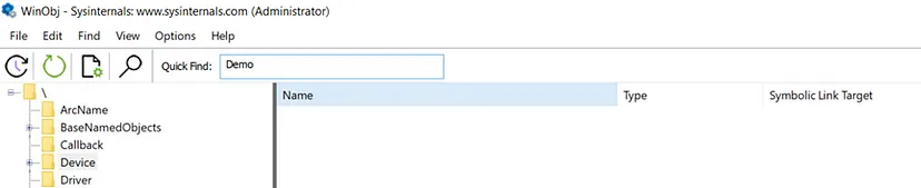
We can also confirm the creation of the “Device Object” in “WinObj.exe”,:
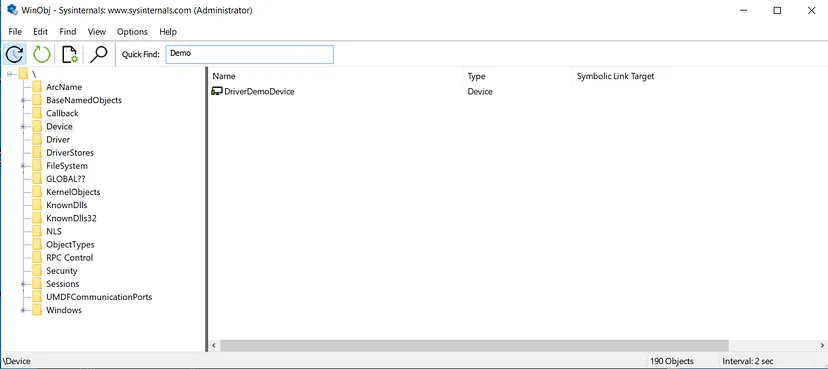
Let’s verify it WinDbg, to do that, we’re going to use the !devobj extension command and put the full path to the device as an argument:
1
!devobj \Device\DriverDemoDevice
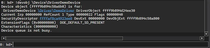
We get the following information out of the command:
The base kernel address of the
_DEVICE_OBJECTstructure of the device.The base kernel address of the
_DRIVER_OBJECTstructure of the driver + the driver’s name.The “Security Descriptor” of the device object itself
Let’s now continue the execution of the machine by executing the “g” command in WinDbg.
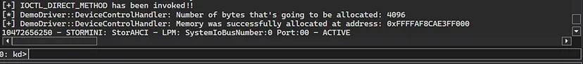
Now, let’s run the “ClientDriverDemo.exe” and see what happens. First, we can see that the kernel verbosity messages prints that the first “DeviceIoControl()” call to the “IOCTL_BUFFERED_METHOD” was invoked successfully and indeed 0x1000 bytes were allocated at the printed address:

The executable’s console prints the message returned from the driver, which also confirms the execution of the IOCTL:

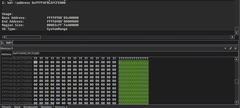
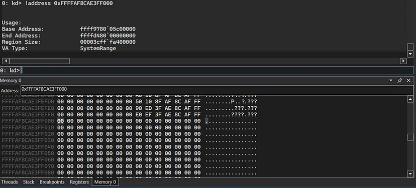
We can see also verify in WinDbg that the memory has been allocated:
1
!address 0xFFFFAF8CAFCFE000
Let’s continue to the second IOCTL (IOCTL_DIRECT_METHOD) call by continuing execution in WinDbg and pressing enter on the client console:

We can see that the IOCTL_DIRECT_METHOD both in the verbosed kernel output and in the client application’s console that the IOCTL was invoked successfully and the memory has been allocated at the outputted address.
We can verify in WinDbg that the memory was allocated:
1
!address 0xFFFFAF8CAFCFE000
The third IOCTL is for the “METHOD_NEITHER” which, as said before, directly interacts with the buffer with no “MDLs”, “System Buffers”, and without any validation:


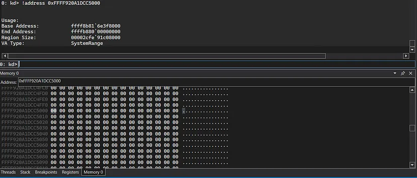
We’ll verify in WinDbg that the memory was allocated:
1
!address 0xFFFF920A1DC5000
The next thing I’d like to show is how we can intercept and view IRP requests coming to the driver. The way I usually do it is by first setting a breakpoint on the start of the DeviceControlHandler() dispatch routine of the driver:
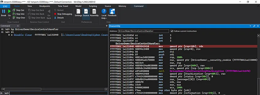
Now let’s continue exuecution in WinDbg and rerun the executable client code in order to invoke the breakpoint:
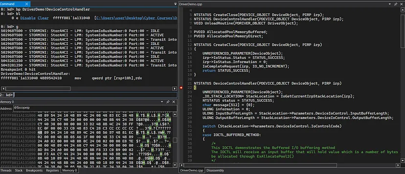
We’re currently at the start of the “DeviceControlHandler()” IOCTL handler dispatch routine (WinDbg is nice enough to show the C code because the code resides in the Visual studio of the debugging machine).
Now, because this is a dispatch routine, every dispatch routine has it’s first argument to be a pointer to the “_DEVICE_OBJECT” structure of the “Device Object”, and the second argument to be the base address of the “_IRP” structure of the IRP. In the x64 calling convention, we know that the first argument to a function is being passed in the “rcx” register, and the second argument is being passed in the “rdx” register.
This means that a pointer to the current IRP structure (which is a request to the IOCTL_METHOD_BUFFERED) resides in the “rdx” register. We can confirm it by executing the following command:
1
dt nt!_IRP @rdx

Let’s view the AssociatedIrp->SystemBuffer field and see if it holds the input buffer that we passed to the driver (which is the 0x1000 size):
1
dx -id 0,0 ffffde09f53af080 -r1 (*((ntkrnlmp!_IRP *)0xffffde09f2c036f0)).AssociatedIrp
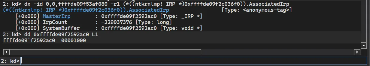
As we can see, the value passed in the buffer is indeed 0x1000. The _IRP structure is very interesting to research, so if you’re not very familiar with it, I encourage you to play with the structure in WinDbg and see what interesting things you can find.
Another thing I would like to show is the !drvobject extension command, which displays information about a driver:
1
!drvobj \Driver\DemoDriver
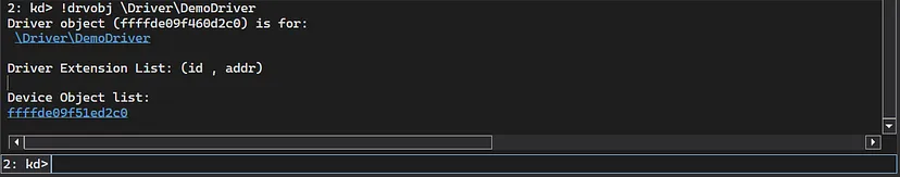
This gives 2 basic details:
- A pointer to the
_DRIVER_OBJECTstructure of the driver - A lists of “Device Objects” that are under the driver, in this case there is only 1.
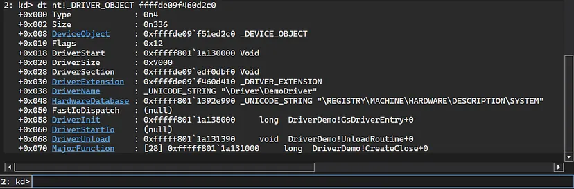
We can view the “_DRIVER_OBJECT” itself to get more side information about the driver:
1
dt nt!_DRIVER_OBJECT ffffde09f460d2c0
Let’s now resume execution of the machine. The last thing that is left for us is to unload the driver, which will invoke the “Unload Routine” to be executed. To do that, we’ll need to execute the following command:
sc stop DemoDriver
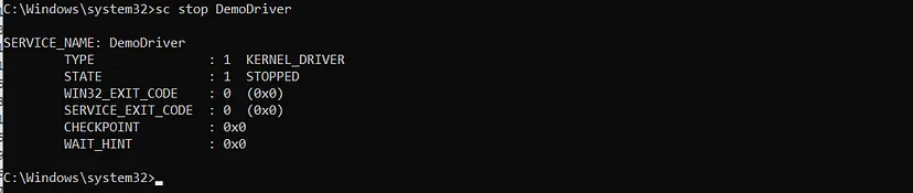
Viewing the verbosed kernel output, we can see that the driver was unloaded successfully and the allocated pool memory were freed:

We can verify it by resuming execution and searching for the device object and the driver object in “WinObj64.exe”:
We can see that there is no device or driver, which confirms that the unload was successful.
All of the code presented in this article is available in my Github page for further inspecting: