Virtualization-Based Security with Hyper-V: Exploring Hyper-V mechanisms and Virtualization Based Security
In the last years, Virtualization Based Security became a major defensive player in the world of low-level binary exploitation, and made it much harder for vulnerability researchers to create a fully working exploit in a mitigated environment. In this article, we’re going to go over the core Hyper-V mechanisms to explain some of the VBS mechanisms available in a modern patched system.
Before starting, if you’re already familiar with the terms: VMCS, SynIC (Synthetic Interrupt Controller), Intercepts and VTLs, then I recommend you move to the “Virtualization Based Security” topic, where I’ll expand about certain VBS mechanisms and demonstrate some of them in IDA.
What is Hyper-V?
Hyper-V is an architecture developed by Microsoft that allows to manage and create Virtual Machines on Windows. To start off, I created a general scheme (Not a full scheme) of Hyper-V which will make life easier for us when we’ll start to go over the architecture itself:

If that’s a bit small, here is a GitHub link to the XML file to drag and drop into “draw.io” website to view the architecture: https://github.com/AmitMoshel1/Hyper-V-General-Scheme/blob/main/Hyper-V%20Architecture%20updated.drawio
Hyper-V relates to a host machine as the “Root Partition” and to the VMs that runs under it as the “Child Partition”.
Each “Child Partition” is mainly consisted out of the following components:
Physical Addressrange that’s allocated to it.Virtual Processors.VTLs– Virtual Trust Levels (under a VP).SynIC– Synthetic Interrupt Controllers (for each VTL in a VP).VMCS– Virtual Machine Control Structure (for eachVTLin aVP).EPT– Extended Page Tables (for eachVTLin aVP).
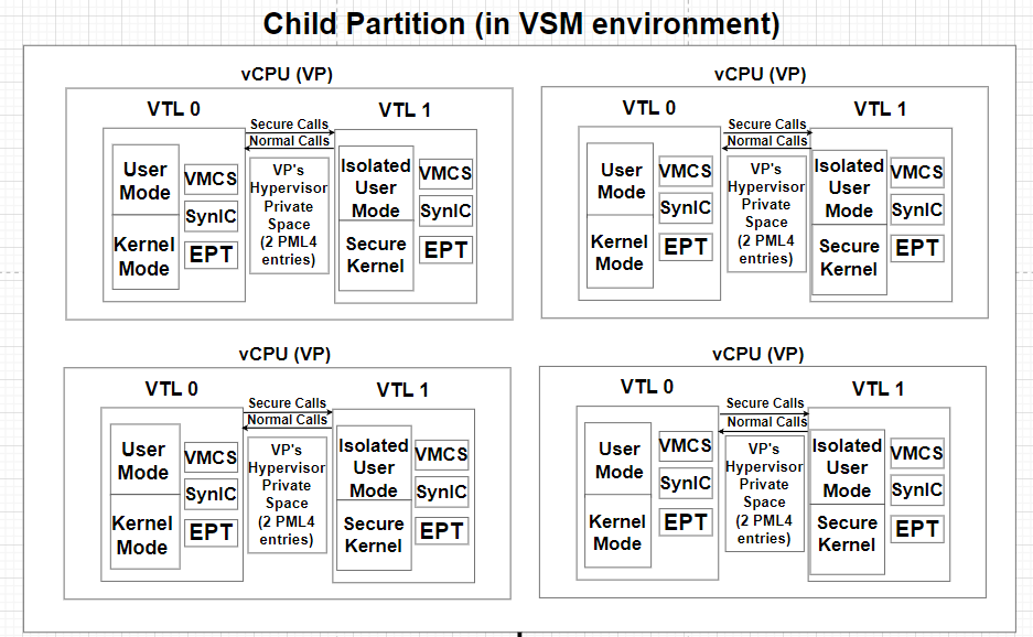
A Virtual Processor (vCPU) in Hyper-V is a virtualized entity that is attached to a physical CPU core on the host machine, allowing a virtual machine to execute tasks.
Each Virtual Processor includes the following components:
VTLs - Virtual Trust Levels
A Virtual Trust Level (VTL) is an Isolated execution unit that runs under a Virtual Processor. Hyper-V supports up to 16 VTLs but currently only 2 VTLs are in use:
VTL 0(Normal World)VTL 1(Secure World)
The higher the VTL, the more privileged the execution state. Each higher VTL has full access to the memory within lower VTLs.
As shown in the scheme above, each VTL holds 3 main components that ensures isolation between each VTL:
EPT - Extended Page Tables
Each partition has its own physical address space that’s allocated to it to ensure safe isolation between each partition. To appropriately manage that, the idea of SLAT (Second Layer Address Translation) came into play.
For clarification, the term SLAT is a general term for second layer translation and EPT is intel’s VT-x implementation of SLAT. Each address that’s being accessed by a Virtual Processor, is going through 2 address translation processes:
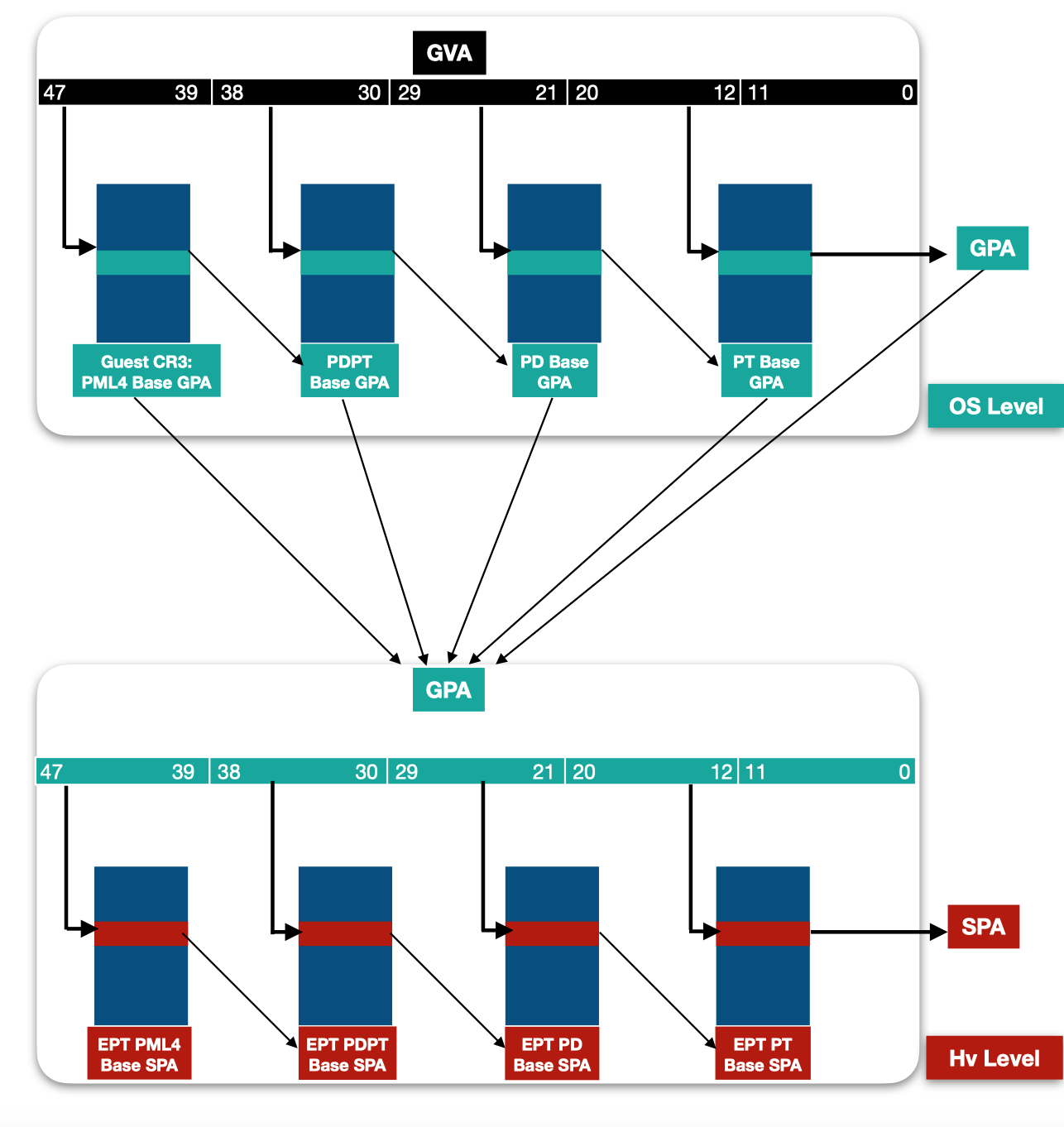
The first layer of address translation involves the translation from a GVA (Guest Virtual Address) to a GPA (Guest Physical Address). This translation process occurs within the OS of the Child Partition.
The second layer of address translation is the EPT which occurs on the Hypervisor level (Ring -1). This translation process is responsible for translating from GPA (Guest Physical Address) to SPA (System Physical Address). SPA is the real physical address that’s accessible.
Each VTL has its appropriate EPT in Hypervisor’s space and is used as a mechanism to ensure isolation between each VTL and between each partition.
The idea of EPT became a real trouble for vulnerability researchers, because even if an attacker has the ability to overwrite a PTE’s permission bits on the OS level for exploitation purposes, still an “Access Violation” exception will occur because the EPT’s PTE still has the same previous permissions, which can’t be modified by an attacker from Ring 0. For more information about this topic, I highly recommend watching Connor McGarr’s lecture on “Off By One Security”:
https://www.youtube.com/watch?v=jWIkhg0Ufr4
VMCS - Virtual Machine Control Structure
A VMCS is a Hypervisor (Ring -1) level structure that’s being held by each VTL and is responsible to hold crucial data that’s being used while transitioning execution from child partition execution to Root Partition and vice-versa.
The fields that reside in VMCS according to intel developer manual:
Guest-state area- Processor state is saved into the guest-state area on VM exits and loaded from there on VM entries.Host-State area- Processor state is loaded from the host-state area on VM exits.VM-Execution control fields- A bitmask that hold fields that control processor behavior in VMX non-root operation. They determine in part the causes ofVMEXIT.VM-EXIT control fields- A bitmask that hold fields that control and determineVMEXITbehaviour.VM-ENTRY control fields- A bitmask that hold fields that control and determineVMENTRYbehaviour.VM-EXIT information fields- Set of fields that hold information on the last VMEXIT and describe the cause and the nature ofVMEXIT.
The instruction that’s being called to initiate the transition from the Hypervisor (VMX-Root operation) to Root/Child Partition (VMX Non-Root operation) is VMENTRY, and the instruction that’s being called to initiate the transition from Root/Child Partition Partition to the Hypervisor is VMEXIT.
Each VTL has its own VMCS fields that reside in Ring -1 to ensure execution state isolation between each VTL and safe transitions between Root and Child partitions. Interactions with VMCS is performed by the following intel VT-x instructions:
VMREAD– Reading a field from VMCS.VMWRITE– Writing a value into a specific field in VMCS.VMPTRLD- Loads the pointer to the current VMCS from the specified address.VMPTRST- Stores the current VMCS pointer into a specified memory address.
SynIC - Synthetic Interrupt Controller
The third component is a more complex topic and is Interrupt management in a virtualized environment.
Each VTL has its own Synthetic Interrupt Controller, which is used locally within a VTL to transfer the interrupt into the OS.
In a virtualized environment, there are 2 types of interrupts:
Synthetic Interrupts– Virtual Interrupts that are invoked from the hypervisor.Physical Interrupts– Interrupts that originates from physical devices.
The function responsible for initializing the SynIC in the Secure Kernel is ShvlpInitializeSynic()
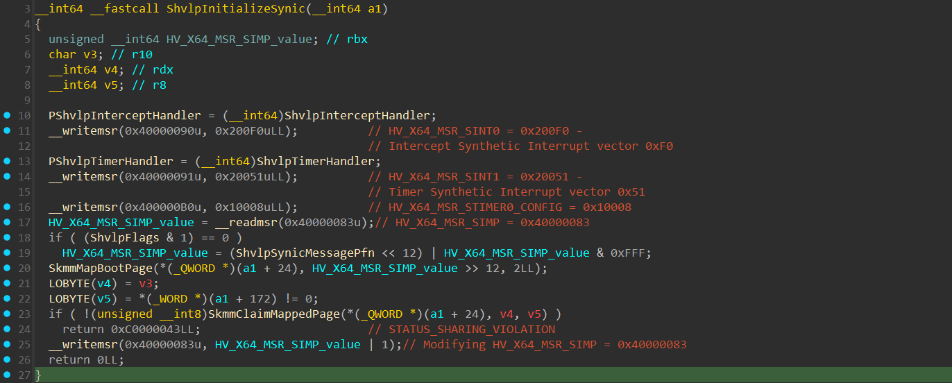
Currently in the Secure Kernel, there are 2 main synthetic interrupts handled:
- Secure Intercepts - At vector 0xF0, handled in the
ShvlpInterceptHandler()function. - Virtualized Timer Interrupts - At vector 0x51, handled in the
ShvlpTimerHandler().
Information about these synthetic interrupts are saved within Virtual MSRs respsonsible for storing information related to the synthetic interrupts, such as their vector number and more :
HV_X64_MSR_SINT0 (0x40000090) -> Holds information about the Secure Intercepts handler.
HV_X64_MSR_SINT1 (0x40000091) -> Holds information about the Synthetic Timer handler.
One of the major uses of the Synthetic Interrupt Controller is to allow inter-partition communication. This is a mechanism that allows partition to transfer 2 types of data:
Messages – Sent using
HvCallPostMessage()hypercall.Events – Sent using
HvSignalEvent()hypercall.
These “Messages” and “Events” are being transferred using a component called VMBus which is implemented as a vmbusr.sys on the Root Partition side and a vmbus.sys on the Child Partitions side.
Each partition is being allocated with a Port ID and a 16 message queues that are being allocated from the partition’s memory pool in the hypervisor’s space (using the HvCreatePort() hypercall and HvConnectPort() hypercall, I’ll explain the idea of hypercalls soon).
Each message (allocated as the HV_MESSAGE structure) within a Message Queue is 256 bytes in size, where the first 16 bytes are the message header (HV_MESSAGE_HEADER data structure).
Whenever a message that is destined to a specific partition is received, it’s being allocated within one of the Message slots in the message queues and when it’s being interacted the target VTL within the appropriate VP, it’s being copied into a special page called “SIMP” (Synthetic Interrupt Message Page), which is a shared page that’s mapped both in the hypervisor’s memory region and in the partition’s and is being interacted while a message needs to be handled using the SynIC of the target VTL.
The following is an image that describes both HV_MESSAGE structure and HV_MESSAGE_HEADER structure:
1
2
3
4
5
6
7
8
9
10
11
12
13
14
15
16
17
18
19
20
21
22
23
24
25
26
27
28
29
#define HV_MESSAGE_SIZE 256
#define HV_MESSAGE_MAX_PAYLOAD_BYTE_COUNT 240
#define HV_MESSAGE_MAX_PAYLOAD_QWORD_COUNT 30

typedef struct
{
   UINT8 MessagePending:1;
   UINT8 Reserved:7;
} HV_MESSAGE_FLAGS;

typedef struct
{
   HV_MESSAGE_TYPE MessageType;
   UINT8 PayloadSize;
   HV_MESSAGE_FLAGS MessageFlags;
   UINT16 Reserved;
   union
   {
       UINT64 OriginationId;
       HV_PARTITION_ID Sender;
       HV_PORT_ID Port;
   };
} HV_MESSAGE_HEADER;

typedef struct
{
   HV_MESSAGE_HEADER Header;
   UINT64 Payload[HV_MESSAGE_MAX_PAYLOAD_QWORD_COUNT];
} HV_MESSAGE;
https://learn.microsoft.com/en-us/virtualization/hyper-v-on-windows/tlfs/datatypes/hv_message
The second type of interrupts are physical interrupts. The idea of handling physical interrupts is highly complex and there are multiple ways of handling it, which in modern mechanisms are safely implemented by in intel VT-d.
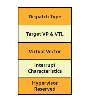
In an extermely simplified explanation, a device generates an MSI/MSI-X by issuing a memory write (DMA operation) to an interrupt remapping address. The IOMMU and interrupt-remapping hardware translate this interrupt according to hypervisor-configured ownership, including the target partition, virtual processor, and VTL. An example for a physical interrupt descriptor under Hyper-V:
https://www.amazon.com/Windows-Internals-Part-2-7th/dp/0135462401
If hardware-assisted interrupt virtualization (Virtual APIC (APICv) / posted interrupts) is enabled and the target VP is running, the interrupt is delivered directly to the guest’s virtual APIC without causing a VM-exit.
Otherwise, the processor triggers a VM-exit, and the hypervisor injects the interrupt into the appropriate virtual processor using VM-entry Interruption Information field within the VMCS of the target VTL.
In both cases, the interrupt is delivered to the guest running in a target VTL. Since VTL1 currently doesn’t support physical interrupts, all of the physical interrupts are managed from VTL0.
Hypercalls
Hypercall is a mechanism relatively similar in its idea to syscalls, and is being used to request a specific service from the hypervisor. Executing “Hypercall” will transition execution to Ring -1.
There are 2 hypercalls mechanisms:
Simple– Which means that the request is relatively simple and can be executed as a single hypercall request.Rep– Designed for more complex requests that take more time to be executed (usually more than a clock tick, which is approximately 15.6ms). Since a hypercall is considered a privileged task, and there might be important events that need to be handled, the “Rep” mechanism is used to divide the main hypercall into a small set of hypercalls that are being executed in parts. This will allow relatively complex hypercalls to still be executed and allow critical tasks to be executed in between.
As from the calling convention perspective, the hypervisor supports 3 calling conventions:
Standard– Takes one GPA (Guest Physical Address) of an input parameter on the rdx register, and oneGPAof an output parameter on r8.Fast– Takes 2 input arguments in rdx and r8.Extended Fast– A calling convention that uses 6XMMregisters to allow the caller to pass an input parameter block up to 112 bytes in size.
Each partition is being allocated with an hypercall page which is used to hold information that’s used for correctly dispatching the hypercalls into the hypervisor.
The first argument of each hypercall, which according to the x64 calling convention resides in the RCX register holds necessary information that describes which function to execute based on a “Call Code” and how the hypercall is going to be executed:
1
2
3
4
5
6
7
8
9
10
11
12
13
14
15
16
17
typedef union _HYPERCALL_INPUT_VALUE
{
    UINT64 Flags;
    struct
    {
        UINT64 CallCode : 16; // HYPERCALL_CODE
        UINT64 Fast : 1;
        UINT64 VariableHeaderSize : 9;
        UINT64 IsNested : 1;
        UINT64 Reserved0 : 5;
        UINT64 RepCount : 12;
        UINT64 Reserved1 : 4;
        UINT64 RepStartIndex : 12;
        UINT64 Reserved2 : 4;
    } Fields;

} HYPERCALL_INPUT_VALUE, *PHYPERCALL_INPUT_VALUE;
https://doxygen.hyperdbg.org/_vmx_8h_source.html
Explanation for each field can be found on MSDN:

https://learn.microsoft.com/en-us/virtualization/hyper-v-on-windows/tlfs/hypercall-interface
The following is an enum called HYPERCALL_CODE that holds a set of hypercall call code values and their target function in the hypervsior:
1
2
3
4
5
6
7
8
9
10
11
12
13
14
15
16
17
18
19
20
21
22
23
24
25
26
27
28
29
30
31
32
33
34
35
36
37
38
39
40
41
42
43
44
45
46
47
48
49
50
51
52
53
54
55
56
57
58
59
60
61
62
63
64
65
66
67
68
69
70
71
72
73
74
75
76
77
78
79
80
81
82
83
84
85
86
87
88
89
90
91
92
93
94
95
96
97
98
99
100
101
102
103
104
105
106
107
108
109
110
111
enum HYPERCALL_CODE
{
    HvSwitchVirtualAddressSpace  = 0x0001,
    HvFlushVirtualAddressSpace   = 0x0002,
    HvFlushVirtualAddressList    = 0x0003,
    HvGetLogicalProcessorRunTime = 0x0004,
    // 0x0005..0x0007 are reserved
    HvCallNotifyLongSpinWait         = 0x0008,
    HvCallParkedVirtualProcessors    = 0x0009,
    HvCallSyntheticClusterIpi        = 0x000B,
    HvCallModifyVtlProtectionMask    = 0x000C,
    HvCallEnablePartitionVtl         = 0x000D,
    HvCallDisablePartitionVtl        = 0x000E,
    HvCallEnableVpVtl                = 0x000F,
    HvCallDisableVpVtl               = 0x0010,
    HvCallVtlCall                    = 0x0011,
    HvCallVtlReturn                  = 0x0012,
    HvCallFlushVirtualAddressSpaceEx = 0x0013,
    HvCallFlushVirtualAddressListEx  = 0x0014,
    HvCallSendSyntheticClusterIpiEx  = 0x0015,
    // 0x0016..0x003F are reserved
    HvCreatePartition         = 0x0040,
    HvInitializePartition     = 0x0041,
    HvFinalizePartition       = 0x0042,
    HvDeletePartition         = 0x0043,
    HvGetPartitionProperty    = 0x0044,
    HvSetPartitionProperty    = 0x0045,
    HvGetPartitionId          = 0x0046,
    HvGetNextChildPartition   = 0x0047,
    HvDepositMemory           = 0x0048,
    HvWithdrawMemory          = 0x0049,
    HvGetMemoryBalance        = 0x004A,
    HvMapGpaPages             = 0x004B,
    HvUnmapGpaPages           = 0x004C,
    HvInstallIntercept        = 0x004D,
    HvCreateVp                = 0x004E,
    HvDeleteVp                = 0x004F,
    HvGetVpRegisters          = 0x0050,
    HvSetVpRegisters          = 0x0051,
    HvTranslateVirtualAddress = 0x0052,
    HvReadGpa                 = 0x0053,
    HvWriteGpa                = 0x0054,
    // 0x0055 is deprecated
    HvClearVirtualInterrupt = 0x0056,
    // 0x0057 is deprecated
    HvDeletePort                    = 0x0058,
    HvConnectPort                   = 0x0059,
    HvGetPortProperty               = 0x005A,
    HvDisconnectPort                = 0x005B,
    HvPostMessage                   = 0x005C,
    HvSignalEvent                   = 0x005D,
    HvSavePartitionState            = 0x005E,
    HvRestorePartitionState         = 0x005F,
    HvInitializeEventLogBufferGroup = 0x0060,
    HvFinalizeEventLogBufferGroup   = 0x0061,
    HvCreateEventLogBuffer          = 0x0062,
    HvDeleteEventLogBuffer          = 0x0063,
    HvMapEventLogBuffer             = 0x0064,
    HvUnmapEventLogBuffer           = 0x0065,
    HvSetEventLogGroupSources       = 0x0066,
    HvReleaseEventLogBuffer         = 0x0067,
    HvFlushEventLogBuffer           = 0x0068,
    HvPostDebugData                 = 0x0069,
    HvRetrieveDebugData             = 0x006A,
    HvResetDebugSession             = 0x006B,
    HvMapStatsPage                  = 0x006C,
    HvUnmapStatsPage                = 0x006D,
    HvCallMapSparseGpaPages         = 0x006E,
    HvCallSetSystemProperty         = 0x006F,
    HvCallSetPortProperty           = 0x0070,
    // 0x0071..0x0075 are reserved
    HvCallAddLogicalProcessor         = 0x0076,
    HvCallRemoveLogicalProcessor      = 0x0077,
    HvCallQueryNumaDistance           = 0x0078,
    HvCallSetLogicalProcessorProperty = 0x0079,
    HvCallGetLogicalProcessorProperty = 0x007A,
    HvCallGetSystemProperty           = 0x007B,
    HvCallMapDeviceInterrupt          = 0x007C,
    HvCallUnmapDeviceInterrupt        = 0x007D,
    HvCallRetargetDeviceInterrupt     = 0x007E,
    // 0x007F is reserved
    HvCallMapDevicePages               = 0x0080,
    HvCallUnmapDevicePages             = 0x0081,
    HvCallAttachDevice                 = 0x0082,
    HvCallDetachDevice                 = 0x0083,
    HvCallNotifyStandbyTransition      = 0x0084,
    HvCallPrepareForSleep              = 0x0085,
    HvCallPrepareForHibernate          = 0x0086,
    HvCallNotifyPartitionEvent         = 0x0087,
    HvCallGetLogicalProcessorRegisters = 0x0088,
    HvCallSetLogicalProcessorRegisters = 0x0089,
    HvCallQueryAssotiatedLpsforMca     = 0x008A,
    HvCallNotifyRingEmpty              = 0x008B,
    HvCallInjectSyntheticMachineCheck  = 0x008C,
    HvCallScrubPartition               = 0x008D,
    HvCallCollectLivedump              = 0x008E,
    HvCallDisableHypervisor            = 0x008F,
    HvCallModifySparseGpaPages         = 0x0090,
    HvCallRegisterInterceptResult      = 0x0091,
    HvCallUnregisterInterceptResult    = 0x0092,
    HvCallAssertVirtualInterrupt       = 0x0094,
    HvCallCreatePort                   = 0x0095,
    HvCallConnectPort                  = 0x0096,
    HvCallGetSpaPageList               = 0x0097,
    // 0x0098 is reserved
    HvCallStartVirtualProcessor = 0x009A,
    HvCallGetVpIndexFromApicId  = 0x009A,
    // 0x009A..0x00AE are reserved
    HvCallFlushGuestPhysicalAddressSpace = 0x00AF,
    HvCallFlushGuestPhysicalAddressList  = 0x00B0
};
https://learn.microsoft.com/en-us/virtualization/hyper-v-on-windows/tlfs/hypercall-interface
The main location from where the hypercalls are being executed at is WinHvr.sys (for Root Partition) and WinHv.sys (for Child Partitions), but can also be executed directly from ntoskrnl.exe.
Let’s view an example for a hypercall in IDA.
In this example, I used the HvlDepositPages(), which is an hypercall that’s defined directly in the kernel (ntoskrnl.exe) and is used to deposit pages from the Root Partition address space to the Child Partition address space:

During the execution, there is a call to nt!HvCallInitiateHypercall:
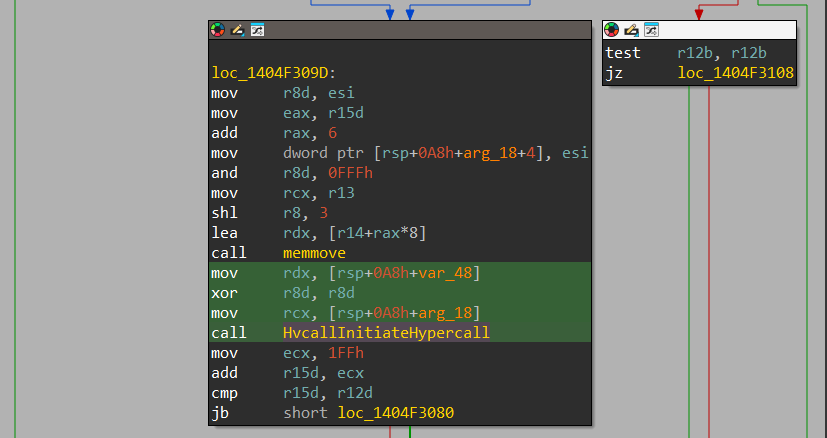
We can see that the first argument in rcx is [rsp+0A8h+arg_18], which is being built during the function implementation, the 2nd argument (rdx) which is the input argument is set with [rsp+0A8h+var_40] and contains data relevant for the function. The 3rd argument is being XORed to 0, which means that no output data is expected.
The Call Code is set relatively at the start and we can see it being set to 0x48:

Viewing “Hypervisor Top Level Functional Specification”, and we can confirm that “Call Code” of 0x0048 indeed refers to HvDepositMemory() hypercall:

Next, HvCallInitiateHypercall() function takes the given arguments based on the calling convention, prepares it and call the HvCallCodeVa():

The HvCallCodeVa() function is being dynamically resolved at runtime and can be found dynamically. This function performs a VMCALL instruction, which is assembly instruction used to directly transfer execution to the Hypervisor.
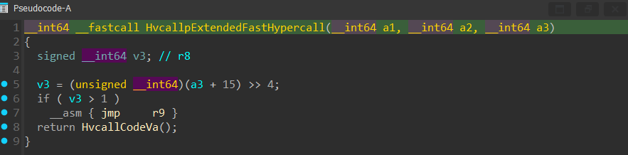
There is also HvCallpExtendedFastHypercall() function, which implements the “Extended Fast Hypercalls” calling convention and also calls the HvCallCodeVa():
Intercepts
During the lifetime of a Child Partition, the child partition may need to interact with one of the following:
- MSRs – read/write
- Execute CPUID instructions
- I/O access operations
- Encounter an exception
- Execute a hypercall
These events are considered sensitive, and can’t be done directly from within the Child Partition without any validation check that the intention of the activity is pure.
For example, if an attacker is able to interact with one of the hypervisor’s related MSR, he can potentially disable sensitive hypervisor related functionality that will allow him to break into the host machine.
For that, an “Intercept” has come into play. “Intercept” is handled differently in 2 scenarios:
- VSM (Virtual Secure Mode) enabled
- VSM disabled
First I’ll start with the VSM disabled, and soon I’ll go in-depth into how “Intercepts” are being handled in a VSM-enabled environment.
Whenever one of the events above are attempted to be executed by a child partition, the hypervisor detects it and causes a VM-Exit that will transfer execution into the hypervisor.
The hypervisor will determine the type of operation being performed and inject a “Synthetic Interrupt” (which as mentioned before, an interrupt that comes from the hypervisor itself) into the Root Partition at vector 0x30 in the IDT of the root partition.
The 0x30 vector is an index within the IDT to executing the nt!KiHvInterrupt ISR, and is one of the 5 ISRs that are related to the virtualization services:
1
!idt

The nt!KiHvInterrupt (in the root partition) eventually calls a specific callback function from a callback table.
The callback function is registered as the intercept handler by initiating a HvInstallIntercept() hypercall from a special driver in Root Partition called vid.sys (Virtualization infrastructure driver) at the partition initialization (for much more information about this driver and virtualization in general, I highly recommend reading the “Windows Internals 7th edition Pt.2”).
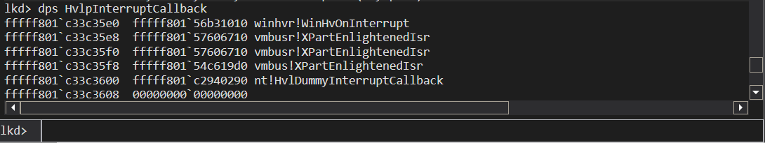
The callback function is called out of a special callback table called HvlpInterruptCallback and this table holds as part of it, a set of intercept callback routines that are used to safely manage the request.
1
dps HvlpInterruptCallback
VBS - Virtualization Based Security
After having the basic information needed to be able to research some of the hyper-v mechanisms. It’s time to see how certain mechanisms in VBS are implemented to isolate execution with VTLs, how the secure world at VTL 1 operates with “Isolated User Mode” (IUM) and “Secure Kernel” (SK).
To enforce VBS on the system, the OS uses multiple interesting DLLs and drivers that are being loaded by the Windows Loader earlier in the boot process:
Skci.dll- responsible for implementing and enforcing the Hypervisor Enforced Code Integrity (HVCI) of the Secure KernelCng.sys- Provides the cryptographic engine to the Secure Kernel.Vmsvcext.dll- Provides support for the attestation of the secure kernel components in Intel TXT (Trusted Boot) environments.
While VTL 0 is considered the “Normal World” with a regular “User-Mode” and “Kernel-Mode”, VTL 1 has its own “IUM” (Isolated User Mode) and “Secure Kernel”.
VTL 1 is used for executing sensitive processes and tasks that need to be isolated from the “Normal World” to prevent unintended actions against sensitive data, such as reading data or executing code in privileged regions of memory.
During the execution in VTLs, there will be cases where one VTL requests services from another VTL, which can be more privileged or less privileged then the requesting VTL. There are 2 main calls:
Secure Call– WhenVTL 0requests service fromVTL 1. Can only come from the regular kernel atVTL 0.Normal Call– WhenVTL 1requests service fromVTL 0. Normal Calls can come both from “Isolated User Mode” (Even if the request was originated from IUM, the transition toVTL 0will come from the “Secure Kernel”) and directly from Secure Kernel.
There are also 2 types of syscalls:
Regular Syscalls– The familiar syscall mechanism that happens inVTL 0
(“Normal World”)Secure Syscalls– TheVTL 1version of syscall execution, from Isolated User Mode to Secure Kernel.
Before practically examining the “Secure Calls”, “Normal Calls” and “Secure System Calls” in IDA, I’d like to shed more light about interrupt scheduling between VTLs. As of today, VTL 1 only handles synthetic interrupts, which are:
- VINA Interrupts (Virtual Interrupt Notification Assist) <- IRQL=4
- Secure Intercepts <– IRQL=15
- Secure IPI (Inter-Processor Interrupts) <– IRQL=14
- Timers <– IRQL=5
- Known Interrupts levels – APC_LEVEL, DPC
Whenever a code is being executed in VTL 0 at a certain IRQL, and an interrupt comes to VTL 1, if the current IRQL at VTL 1 is lesser than the incoming IRQL in VTL 1, then the VTL 1 interrupt will be prioritized and handled. If VTL 1’s current IRQL is higher than the incoming Interrupt, then the incoming interrupt will be queued to VTL 1’s interrupt queue.
The only factor that decides whether to transfer execution to VTL 1 and execute the Interrupt is the IRQL of VTL 1 and not the IRQL of VTL 0.
If code is being executed at VTL 1 at a certain IRQL (lower than the VINA IRQL, which I’ll explain), and an important interrupt (higher in IRQL number than both current interrupt and current VTL 1 interrupt) comes and destined at VTL 0. The hypervisor will detect it and inject a synthetic interrupt to VTL 1 to handle it. The interrupt that will be injected is called VINA (“Virtual Interrupt Notification Assist”). This is an interrupt that’s responsible to perform the “Normal Call” transition into VTL 0, and make VTL 0 handle the incoming interrupt.
In a case where code is executing in VTL 1 and the IRQL of the interrupt that’s being executed is higher than 4 (VINA), no interrupt coming to VTL 0 will be able to receive priority over the currently executing interrupt. This means that even if an important interrupt would be invoked to VTL 0, a VINA interrupt wouldn’t be able to be injected, since the IRQL of VTL 1 is higher in its level over the IRQL of a VINA interrupt that will be injected.
The next thing I’d like to do is to demonstrate the VINA handler routine. But before that, it’s important to know that most of the registers are shared between when transitioning from VTLs (besides RIP, RSP, sensitive CR registers (CR0, CR3, CR4) and sensitive MSRs), especially when transitioning from VTL 0 to VTL 1 using a “Secure Call”. Whenever transitioning from VTL 1 to VTL 0 in “Normal Calls”, the “Secure Kernel” makes sure to perform the appropriate cleaning of registers before transitioning to prevent potential vulnerabilities or data disclosure that can potentially arise from sharing some registers in VTL 0.
Let’s view how the VINA interrupt is being handled in the “Secure Kernel” (VTL 1’s kernel) using the ShvlVinaHandler() routine:
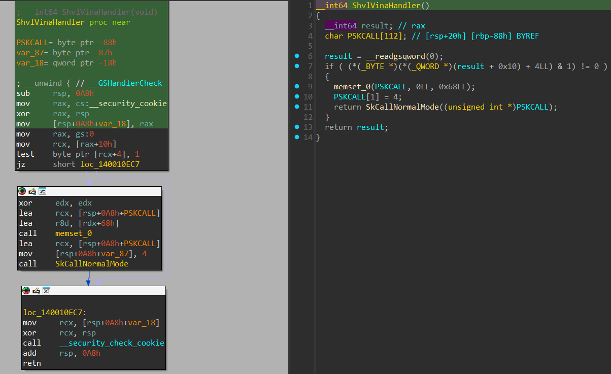
The ShvlVinaHandler() allocates an internal data structure that’s used in both “Normal Calls” and “Secure Calls” and according to “Windows Internals 7th edition Pt.2” book: “SKCALL is 104-byte (0x68) data structure used to describe the kind of operation (invoke service, flush TB, resume thread, or call enclave), the secure call number, and a maximum of 12 8-byte parameters.”
After initializing it, a call to SkCallNormalMode() is invoked, with the pointer to the SKCALL data structure:
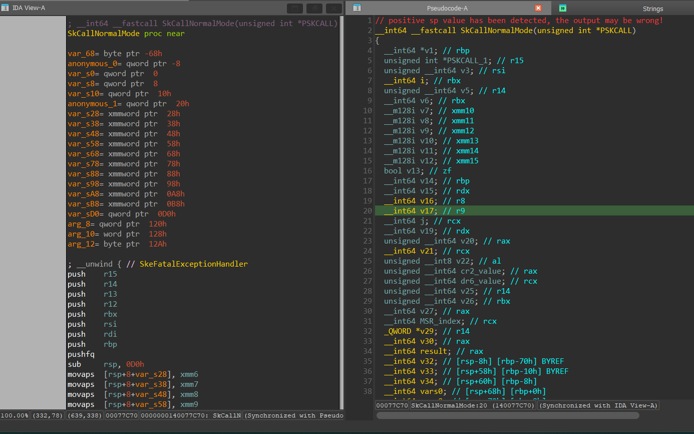
In SkCallNormalMode(), the arguments that were passed into the SKCALL data structures are being copied to shared XMM registers and into the “rbx register, in the assembly below, we can see it’s XMM10-XMM15.
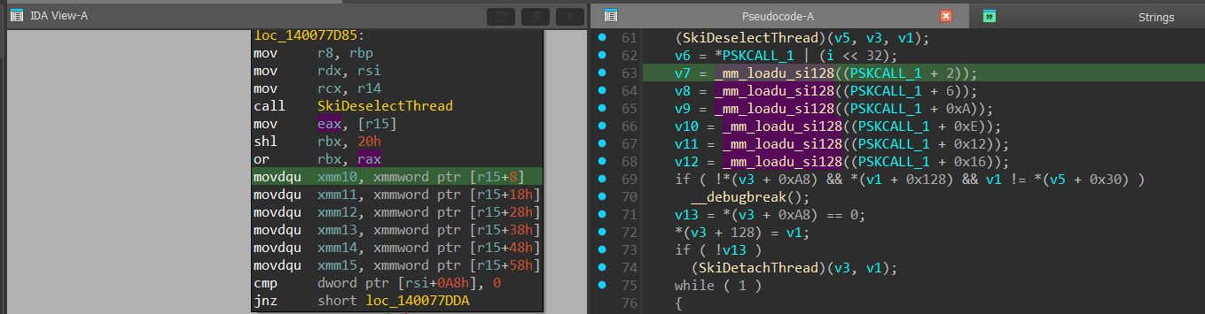
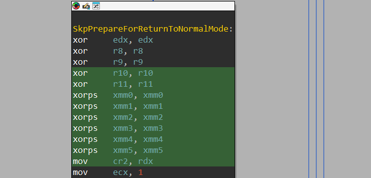
Next, we can see that there is label called SkpPrepareForReturnToNormalMode, which is responsible for cleaning the shared CPU registers (as said before, before transitioning from VTL 1 to VTL 0 it’s important to clean the sensitive registers that are shared before transitioning). In the SkpPrepareForReturnToNormalMode, the registers that are being cleaned using xor and xorps instructions are: edx, r8-r11, xmm0-xmm5

And right after it, a call to ShvlpVtlReturn() is performed. The ShvlpVtlReturn() is responsible to invoke a “VTL Return” hypercall, which is responsible through the hypervisor to transition the execution to VTL 0 and land in the “Interrupt Service Routine” in VTL 0 that caused the hypervisor to inject the VINA interrupt.
Normal Calls
As said before, “Normal Calls” are calls that transfer execution from VTL 1 to VTL 0 and occur when VTL 1 requests services from VTL 0. A “Normal Call” can be originated both from IUM - Isolated User Mode (because ntdll.dll is mapped also in VTL 1 and allows the same SCN to be detected in the secure kernel and transfer execution to VTL 0) and from Secure Kernel.
Since transferring execution from VTL 1 to VTL 0 can be considered a sensitive operation, a safe way to transfer additional data is required. To handle that, the first “Normal Call” that was executed was to MmAllocateVirtualMemory(), which will be used to create a shared buffer mapped in both VTL 0 and VTL 1 and is considered a safe-zone to transfer data between VTL 1 and VTL 0.
Since both “Normal Calls” and “Secure System Calls” uses SCN (System Call Number), there needs to be a way to differentiate between a “Normal Call” that needs to get to VTL 0, and a “Secure System Call” that comes from IUM and needs to execute an internal function within the Secure Kernel. For that, there are specific bits within the SCN that tells the secure kernel whether the request is a “Secure System Call” or a “Normal Call”. There is more data that resides under the SCN and is shown in the image above taken from “Windows Internals 7th edition Pt.2”:
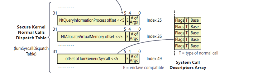

From the images above, we can see that the SCN holds the following data within it:
bit 0-4: Number of arguments that were passed to the function
bit 4-5: does the function supports “enclave” (a VBS feature that I won’t expand on, feel free to view VBS enclaves on MSDN).
bit 5-31: when byte shifted to the left 5 times, holds the offset to the function from the
IumSyscallDispatchTabledescribed above.bit 26-27: Set to 1 when the request is a “Secure System Call”.
bit 30-31: Set to 1 when the request is a “Normal Call”.
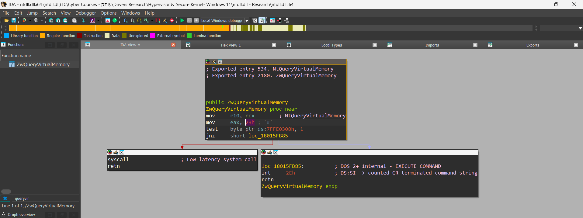
Next, we’ll demonstrate how the “Normal Call” is executed. The demonstration will be for the NtQueryVirtualMemory function. This is how the IumSyscallDispEntries looks like in the “Secure Kernel”:
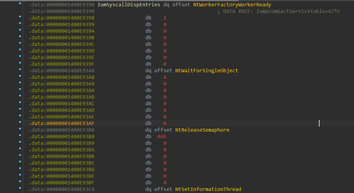
The secure kernel receives the SCN number, which is a normal syscall from “ntdll.dll”, which is mapped both in VTL 0 and VTL 1 memory. Then, the “Secure Kernel” uses the SCN to get into the offset of NtQueryVirtualMemory():

As we can see, both in the previous image, the number 23h is shown under NtQueryVirtualMemory() and both in “ntdll.dll” the syscall number of 23h is shown, which proves that it uses the same SSN mechanism used in “ntdll.dll”
Next, execution gets into the Secure Kernel’s NtQueryVirtualMemory():

The NtQueryVirtualMemory() prepares the arguments for the SkMmQueryVirtualMemory() function:

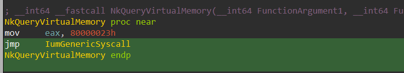
The SkMmQueryVirtualMemory() is relatively long function, which eventually calls NkQueryVirtualMemory() function:

The NkQueryVirtualMemory() transfers another syscall number to the “eax” register, in this case it’s 0x80000023. This is the syscall number that will be used by the secure kernel to parse the information shown 6 images above:
Let’s convert the syscall number to bits:
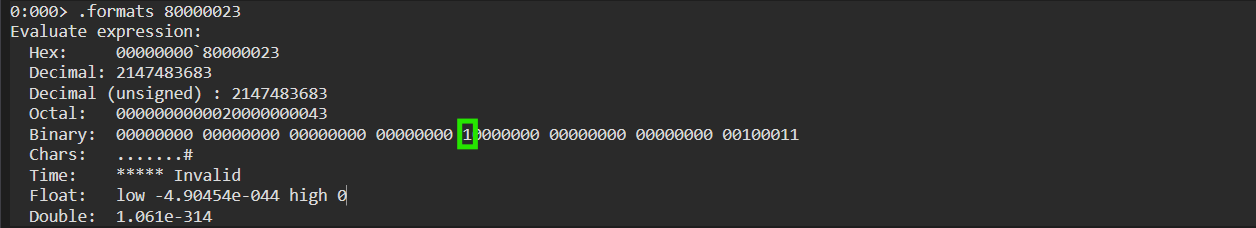
We can see in green that bit 30-31 is set to 1, which confirms that it’s a “Normal Call” call and not a “Secure System Call”. Next, a jmp to IumGenericSyscall occurs:
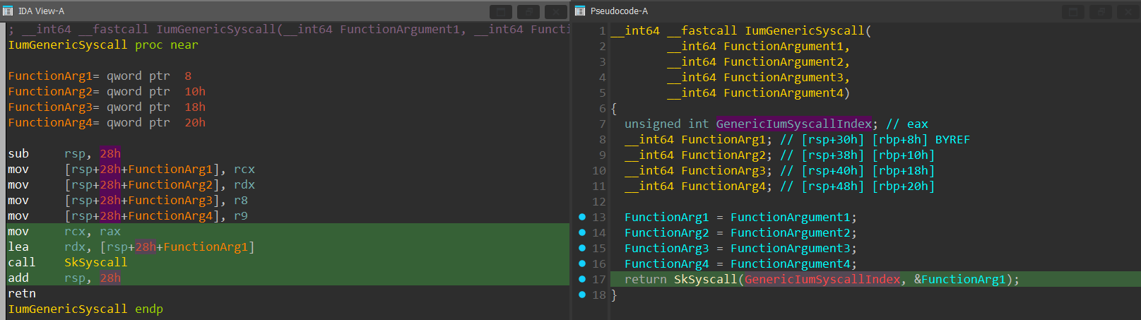
The IumGenericSyscall is a key function in the execution of “Normal Calls”. The function allocates 5 local QWORDs into the stack (a total of 8 bytes x 5 = 40 bytes (28h)) and transfers the first 4 arguments (rcx, rdx, r8, r9) into the expanded stack.
After that, the syscall index in “rax” is passed into the “rcx” register as the first argument for the SkSyscall() function and the base address of the expanded stack is passed into the “rdx” register as the second argument.
The SkSyscall() function is a function responsible for detecting if the syscall is a “Normal Call” or a “Secure System Call”, prepare the shared syscall buffer that will be used to transfer additional data from VTL 1 to VTL 0:
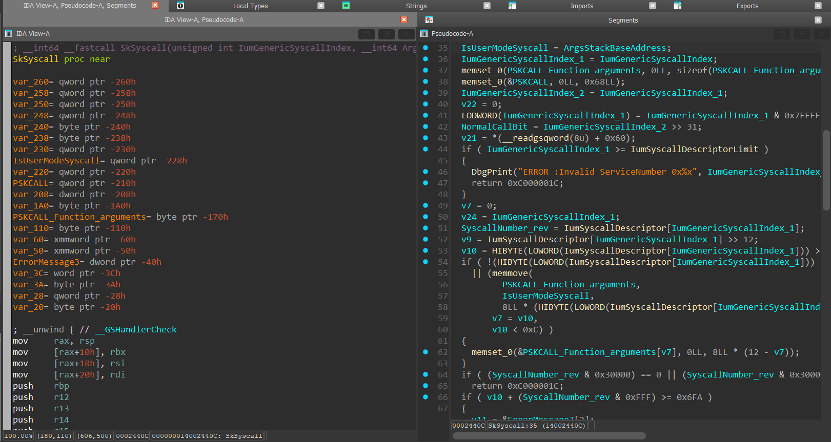
The function starts with the allocation of the already-familiar SKCALL data structure. and the 12 QWORD (8 bytes) arguments that will be copied into the SKCALL data structure:

Next, the function extracts the “Normal Call” bit and saves it into a variable:

Next, the function copies the arguments from the stack, which its base address were passed as the second argument, to the “PSKCALL_Function_arguments” using the memmove() function:

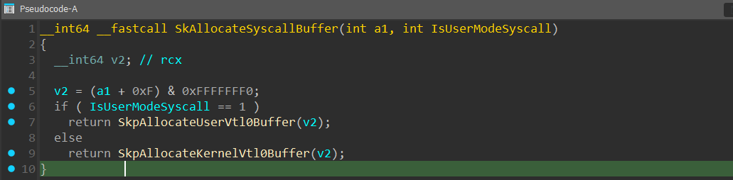
After that, a call to SkAllocateSyscallBuffer() function is performed, which is used to allocate the mutual buffer to transfer additional information between the VTLs if needed:
Continuing with SkSyscall, a call to IumApi_NtGeneric is performed and after that a call to SkCallNormalMode() with the pointer to the SKCALL data structure passed as the first argument:

SkCallNormalMode() is a function we already saw in the ShvlVinaHandler() so I’ll briefly go over it again:
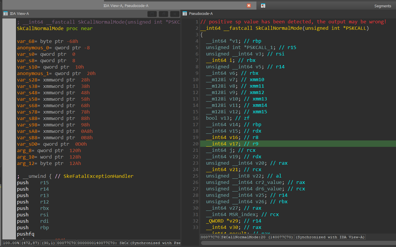
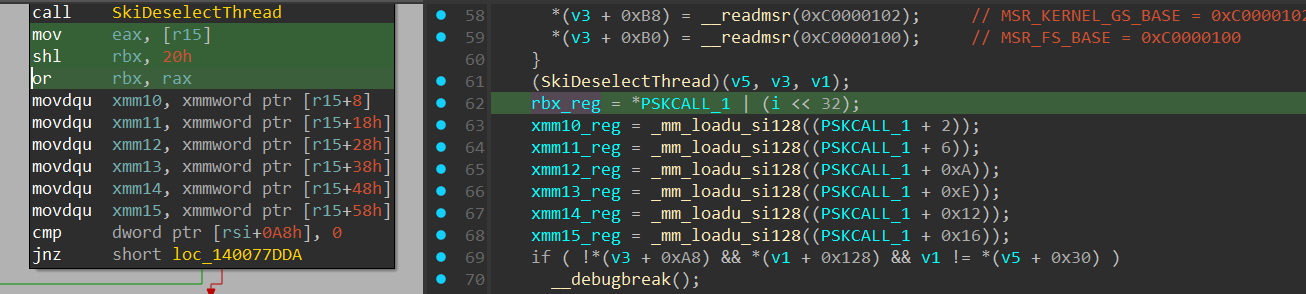
The function copies the arguments from SKCALL to XMM10-XMM15 and into the “rbx” register:
After that, the clearance of the shared CPU registers before transitioning from VTL 1 to VTL 0 is performed:
and a call to ShvlpVtlReturn() which causes a “VTL Return” to VTL 0:

Secure System Calls
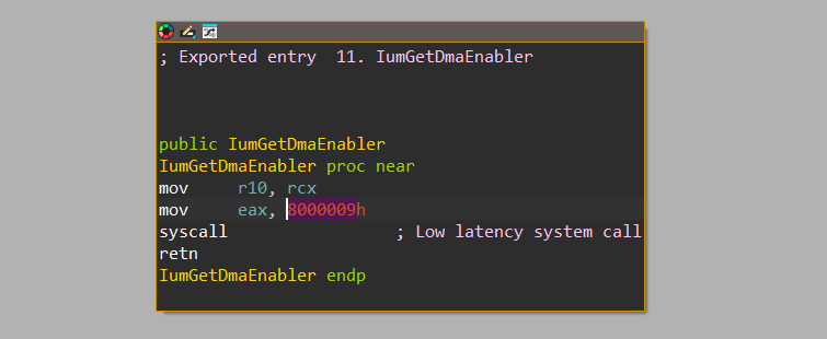
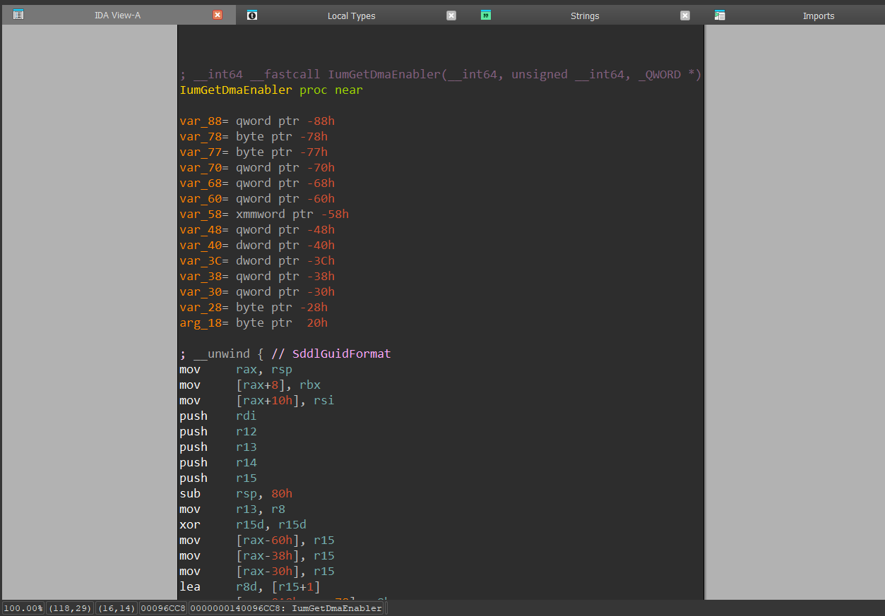
Secure System Calls are originally called from “iumdll.dll” in “Isolated User Mode” and are being executed inside the “Secure Kernel”. Here is an example of a IUM syscall from ”iumdll.dll”, specifically a function called IumGetDmaEnabler:
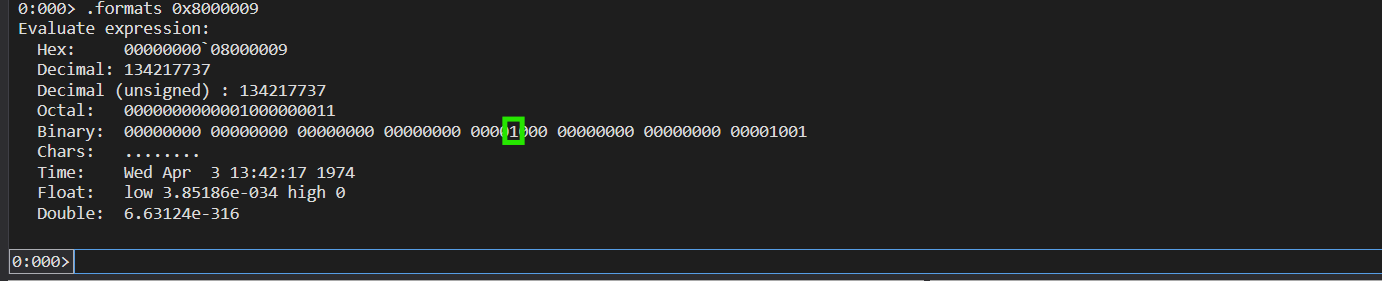
Viewing its bits in WinDbg, we can see that bit 27-28 is indeed set to 1, which means that it’s a “Secure System Call” in this basic example.
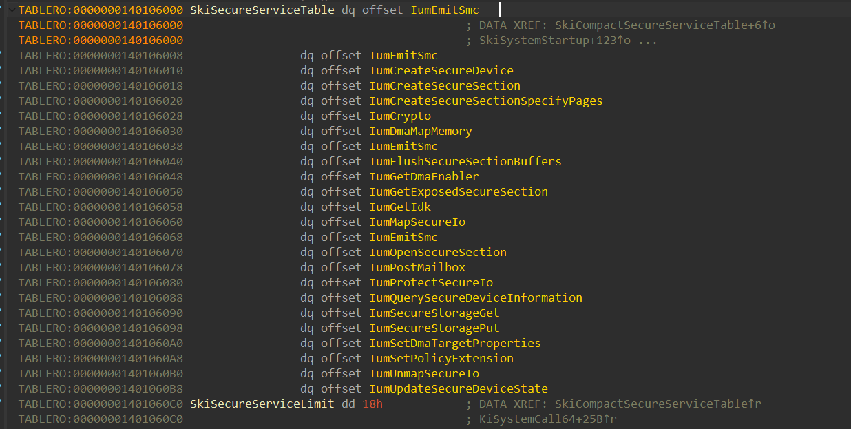
When executing the syscall, the execution transitions from IUM to the Secure Kernel, which uses the SkiSecureServiceTable to determine the location of the secure kernel implementation of that function (in our example, the function is IumGetDmaEnabler()):
and directly gets into the IumGetDmaEnabler() implementation:
Secure Calls
Secure Calls originally starts from the NT kernel at VTL 0 and gets into the Secure Kernel at VTL 1 for executing the Secure Call. I’m going to show the flow of the Secure Call execution through a Secure Thread creation.
Let’s start from VslCreateSecureThread():
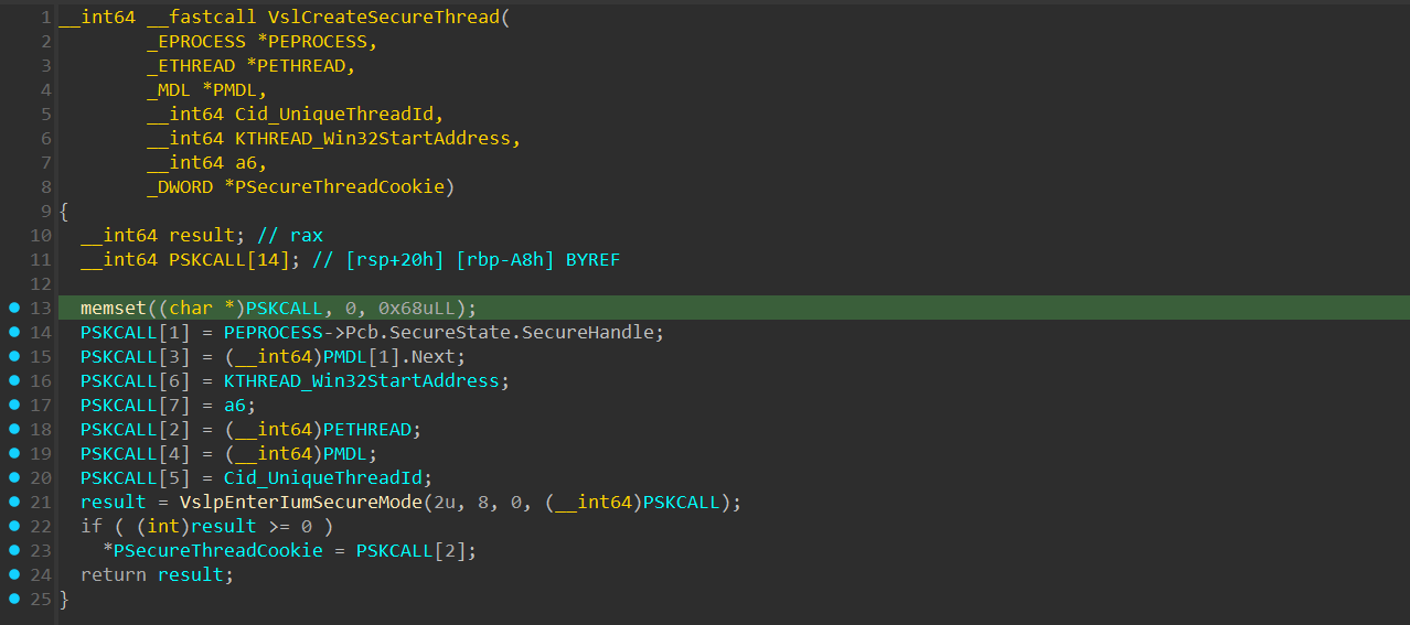
Most of the functions that invoke a “Secure Call” operation will start with the Vsl prefix in their name.
The function takes multiple arguments, allocates a clear SKCALL data structure, and fills the SKCALL data structure with arguments such as:
SecureHandle- The Secure Handle of the secure process that the thread will run under.MDL- A pointer to anMDLwhich is allocated and initialized inPspCreateSecureThread():
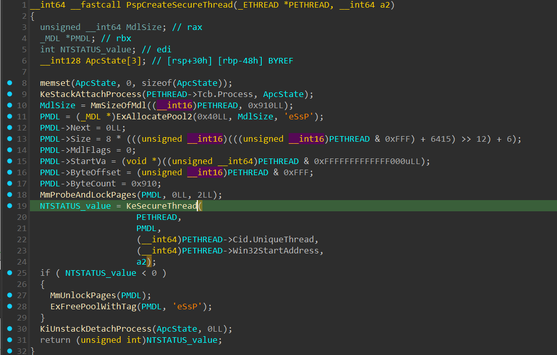
PETHREAD- A pointer of the allocated_ETHREADof the “Secure Thread”.CID- ACLIENT_IDdata that describes the PID and TID of the “Secure Thread”.Win32StartAddress
Next, after filling the SKCALL data structure, a call to VslpEnterIumSecureMode() is created that takes the following arguments:
OperationType- Describes the type of operation to be performed:- invoke service
- flush TB
- resume thread
- call enclave
In this case, my assumption is that the value “2” is to “Invoke Service”, which is the Secure thread creation secure service.
SSCN- Secure Service Call Number. In this case set to 0x8, which will come into play when execution will get into the “Secure Kernel”.SecureThreadCookie- A DWORD value that describes which secure thread will handle the “Secure Call” request, if the value is 0, a “Secure Thread” from the “Secure Thread Pool” will execute the “Secure Call”.PSKCALL- A pointer to the initializedSKCALLdata structure.
In VslpEnterIumSecureMode():
The VslpEnterIumSecureMode() function starts by validating that the environment where the VslpEnterIumSecureMode() has VSM (Virtual Secure Mode) enabled:
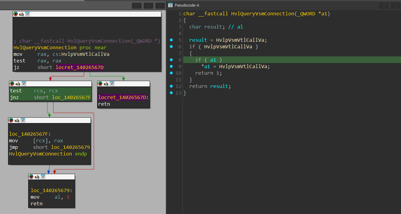
The function starts by checking if the global variable pointer called HvlpVsmVtlCallVa is initialized. HvlpVsmVtlCallVa is a pointer to an assembly block that’s initialized at runtime when VSM is enabled that’s responsible for performing a VTL Call call, which will eventually cause execution to transition to VTL 1.
If HvlpVsmVtlCallVa is indeed initialized, its value will be set in the dereferenced “a1” pointer and the function will return 1, else, it will return 0.
If the returned value answers the “if” statement, VslpEnterIumSecureMode() will return a 0xC000009D NTSTATUS value, which is STATUS_DEVICE_NOT_CONNECTED:

in IDA the argument is set to 0, but when dynamically debugging, there should be a different value.
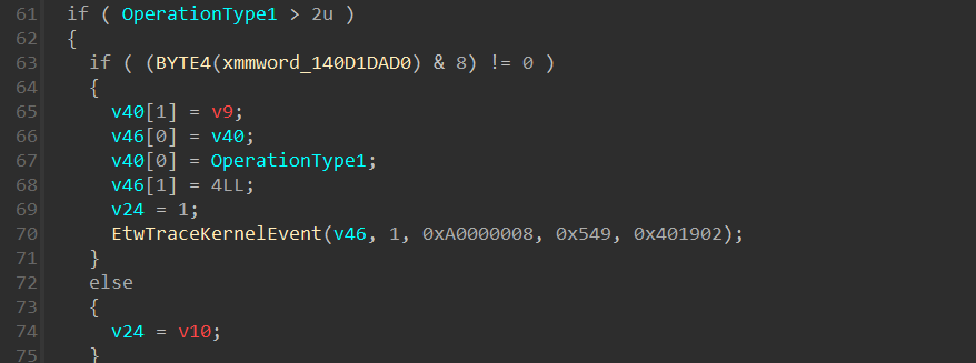
Following that, there is an “if” statement that checks if the OperationType argument is bigger than 2, in our case it’s equal to 2, so we won’t get into that “if” statement:
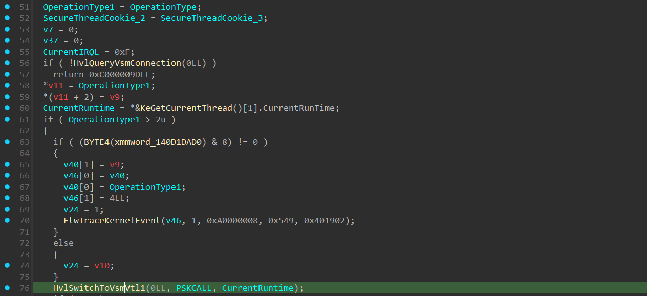
Next, a call to HvlSwitchToVsmVtl1() is executed:
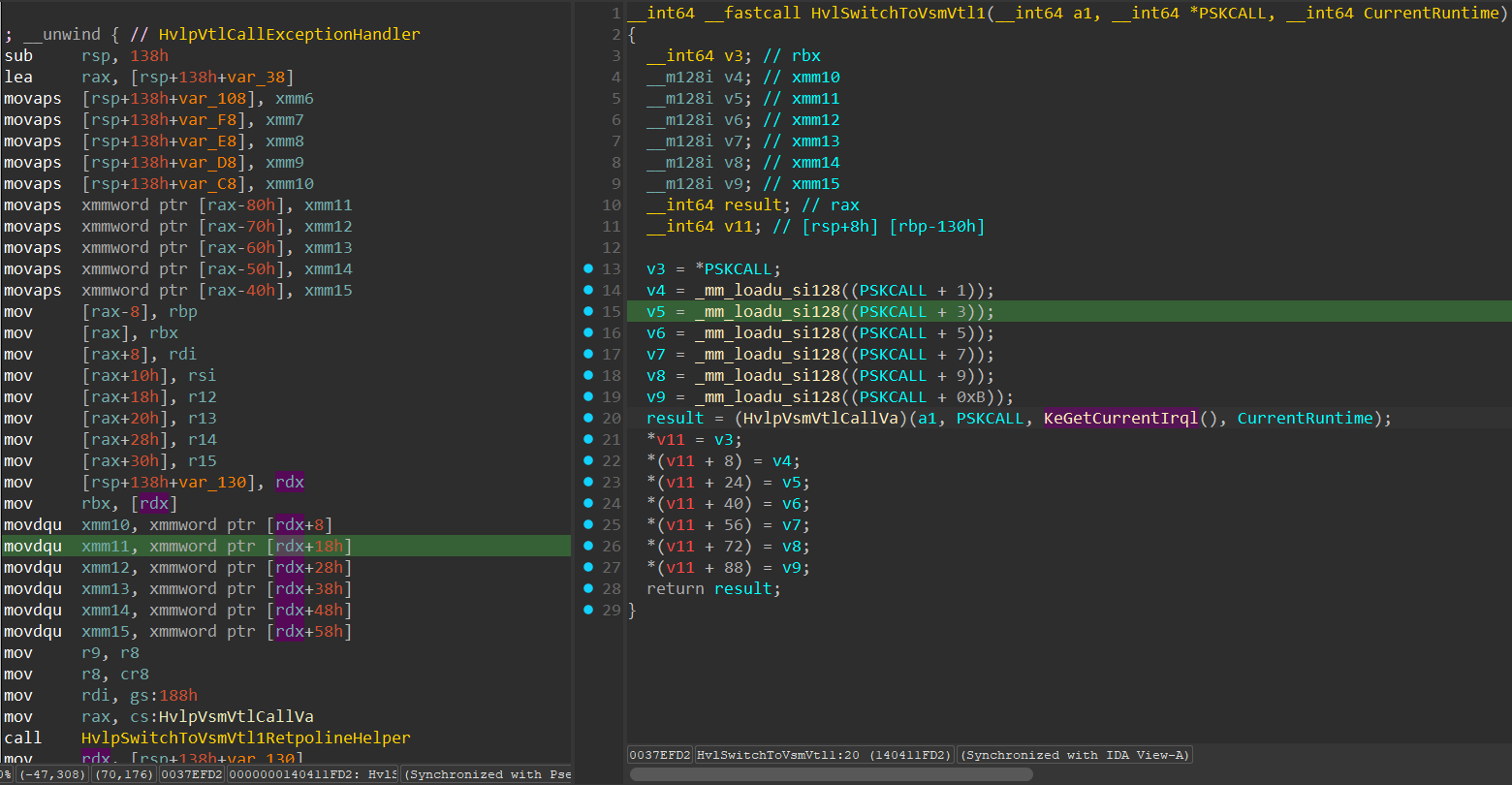
This function transfers the arguments from the SKCALL data structure, to the “rbx” and xmm10-xmm15 registers, similar to what we’ve seen in the “Normal Calls”.
Next, an indirect call to HvlpVsmVtlCallVa() is performed, which transitions the execution to the secure kernel in VTL 1 through a VTL Call. The VTL Call invokes a VMEXIT into the hypervisor, which determines the VMEXIT reason, detects that it’s a VTL Call, update a data structure called HV_VP_VTL_CONTROL is a data structure that’s used in the hypervisor to keep track of the VTL’s state.
This data structure resides in the HV_VP_ASSIST_PAGE data structure, which is a data structure mapped both in the hypervisor’s memory and in the partititon’s memory and is used for sharing data between the hypervisor and the VP under the partition.
1
2
3
4
5
6
7
8
9
10
11
12
13
14
15
16
17
18
19
20
21
22
23
24
25
26
27
28
29
30
31
32
33
34
35
36
37
38
39
40
41
42
43
44
45
typedef enum
{
    HvVtlEntryReserved = 0, // This reason is reserved and is not used.
    HvVtlEntryVtlCall = 1,  // Indicates entry due to a `VTL` call from a lower `VTL`.
    HvVtlEntryInterrupt = 2 // Indicates entry due to an interrupt targeted to the `VTL`.
} HV_VTL_ENTRY_REASON;

typedef struct
{
    // The hypervisor updates the entry reason with an indication as to why
    // the `VTL` was entered on the virtual processor.
    HV_VTL_ENTRY_REASON EntryReason;

    union
    {
        UINT8 AsUINT8;
        struct
        {
            UINT8 VinaAsserted :1;
            UINT8 VinaReservedZ :7;
        };
    } VinaStatus; // This flag determines whether the VINA interrupt line is asserted.

    UINT8 ReservedZ00;
    UINT16 ReservedZ01;

    // A guest updates the VtlReturn* fields to provide the register values
    // to restore on `VTL` return. The specific register values that are
    // restored will vary based on whether the `VTL` is 32-bit or 64-bit.
    union
    {
        struct
        {
            UINT64 VtlReturnX64Rax;
            UINT64 VtlReturnX64Rcx;
        };
        struct
        {
            UINT32 VtlReturnX86Eax;
            UINT32 VtlReturnX86Ecx;
            UINT32 VtlReturnX86Edx;
            UINT32 ReservedZ1;
        };
    };
} HV_VP_VTL_CONTROL;
Whenever there is a VTL Call, the HV_VTL_ENTRY_REASON within the HV_VP_VTL_CONTROL holds the enum value of HvVtlEntryVtlCall. Next, after the hypervisor finishes the preparation for the VTL 1 Entry, the execution lands in the “Secure Kernel”, specifically in the SkCallNormalMode() function which we’ve already seen.
in the SkCallNormalMode() function, there is a specific “if” statement that’s relevant for us:
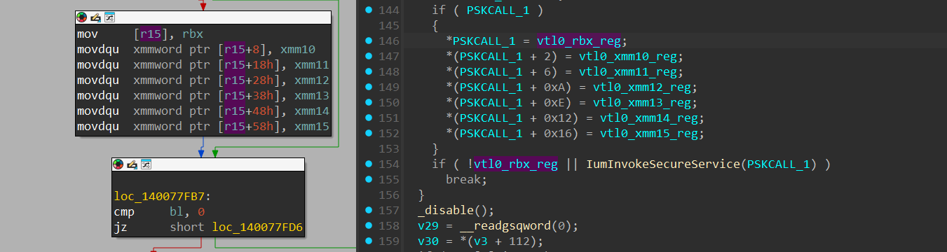
Within it, the xmm10-xmm15 registers values are being copied to a VTL 1 SKCALL data structure. Which leads to another “if” statement that calls the IumInvokeSecureService() function. The IumInvokeSecureService() is a key function when handling “Secure Calls” coming from VTL 0. As previously said, in the second argument in the VslpEnterIumSecureMode() in VTL 0, the second argument was the SSCN”(Secure Service Call Number), which has a similar idea to regular “syscalls”.
The IumInvokeSecureService() holds a “switch()” statement used for handling each SSCN:
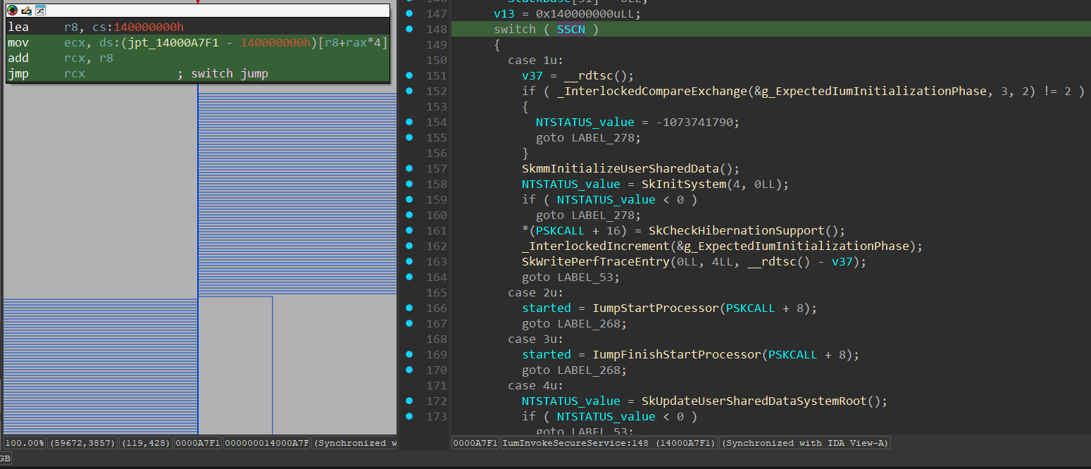
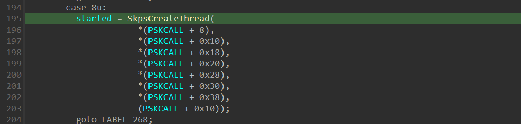
In our case as we’ve seen previously, the SSCN passed to VslpEnterIumSecureMode() is 0x8. Viewing the case of 0x8 in the “switch()” statement, we can see there is a call for SkpsCreateThread() secure kernel function:
Secure Intercepts
As already mentioned before, Intercepts have 2 types of handling, one in an environment where VBS is enabled, and the second in a regular virtualized environment.
In a case where VBS is enabled, one of the previously mentioned Intercept events will invoke a VMEXIT in to the hypervisor, which will examine the VM_EXIT_REASON field within the VMCS, detects that it’s related to an Intercept event, allocate a message structure of type HV_MESSAGE, which looks like this:
1
2
3
4
5
6
7
8
9
10
11
12
13
14
15
16
17
18
19
20
21
22
23
24
25
26
27
28
29
#define HV_MESSAGE_SIZE 256
#define HV_MESSAGE_MAX_PAYLOAD_BYTE_COUNT 240
#define HV_MESSAGE_MAX_PAYLOAD_QWORD_COUNT 30

typedef struct
{
   UINT8 MessagePending:1;
   UINT8 Reserved:7;
} HV_MESSAGE_FLAGS;

typedef struct
{
   HV_MESSAGE_TYPE MessageType;
   UINT8 PayloadSize;
   HV_MESSAGE_FLAGS MessageFlags;
   UINT16 Reserved;
   union
   {
       UINT64 OriginationId;
       HV_PARTITION_ID Sender;
       HV_PORT_ID Port;
   };
} HV_MESSAGE_HEADER;

typedef struct
{
   HV_MESSAGE_HEADER Header;
   UINT64 Payload[HV_MESSAGE_MAX_PAYLOAD_QWORD_COUNT];
} HV_MESSAGE;
https://learn.microsoft.com/en-us/virtualization/hyper-v-on-windows/tlfs/datatypes/hv_message
The first field in the HV_MESSAGE data structure, is an HV_MESSAGE_HEADER data structure, which has the first field of HV_MESSAGE_TYPE:
1
2
3
4
5
6
7
8
9
10
11
12
13
14
15
16
17
18
19
20
21
22
23
24
25
26
27
28
29
30
31
#define HV_MESSAGE_TYPE_HYPERVISOR_MASK 0x80000000

typedef enum
{
   HvMessageTypeNone = 0x00000000,

   // Memory access messages
   HvMessageTypeUnmappedGpa = 0x80000000,
   HvMessageTypeGpaIntercept = 0x80000001,

   // Timer notifications
   HvMessageTimerExpired = 0x80000010,

   // Error messages
   HvMessageTypeInvalidVpRegisterValue = 0x80000020,
   HvMessageTypeUnrecoverableException = 0x80000021,
   HvMessageTypeUnsupportedFeature = 0x80000022,
   HvMessageTypeTlbPageSizeMismatch = 0x80000023,

   // Hypercall intercept
   HvMessageTypeHypercallIntercept = 0x80000050,

   // Platform-specific processor intercept messages
   HvMessageTypeX64IoPortIntercept = 0x80010000,
   HvMessageTypeMsrIntercept = 0x80010001,
   HvMessageTypeX64CpuidIntercept = 0x80010002,
   HvMessageTypeExceptionIntercept = 0x80010003,
   HvMessageTypeX64ApicEoi = 0x80010004,
   HvMessageTypeX64LegacyFpError = 0x80010005,
   HvMessageTypeRegisterIntercept = 0x80010006,
} HV_MESSAGE_TYPE;
https://learn.microsoft.com/en-us/virtualization/hyper-v-on-windows/tlfs/datatypes/hv_message_type
When the hypervisor detects the type of intercept event, it appropriately sets the matches HV_MESSAGE_TYPE index, and constructs the appropriate payload within the “Payload” field in HV_MESSAGE data structure.
After performing the necessary action in the hypervisor, the hypervisor allocates the HV_MESSAGE within the “Message Queue” of the VP (Virtual Processor), and transfers the handling into the SynIC of VTL 1 of the VP. The SynIC transfers the execution into the Secure Kernel, which checks its Secure IDT (Interrupt Dispatch Table) and raises the IRQL of the processor.
The ISR that will be invoked is ShvlpInterceptHandler():
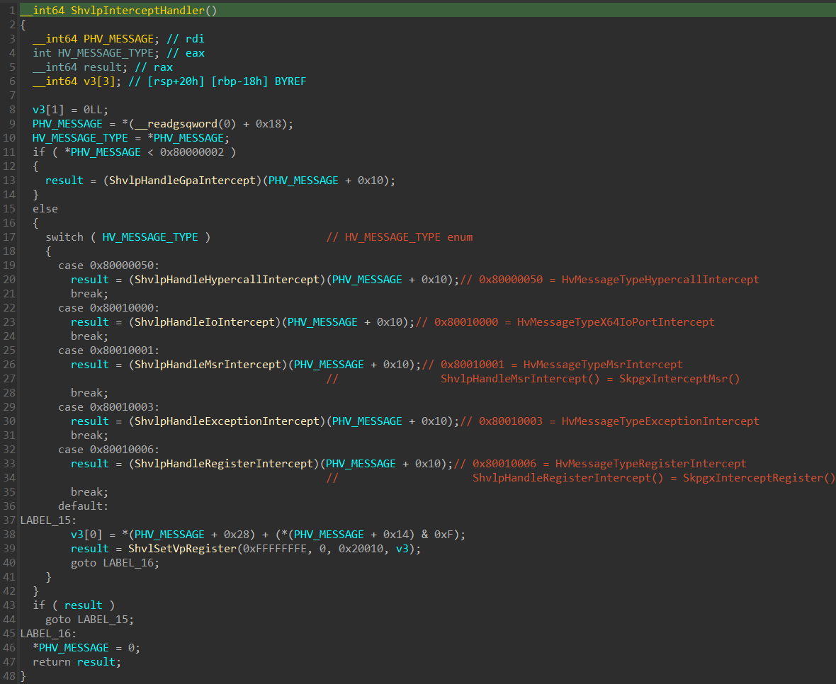
The function starts by getting the base address of HV_MESSAGE structure, dereferences it and gets the enum value of HV_MESSAGE_TYPE which is used for determining the type intercept. After obtaining the HV_MESSAGE_TYPE value, the function uses an “if” and “switch()” statements to invoke the right “Secure Intercept Handler Routine”.
When statically viewing the global pointers to functions like ShvlpHandleMsrIntercept() and ShvlpHandleRegisterIntercept:

we can see that they are not pre-defined statically. Viewing the XREFs of these global pointers, we can see that they are defined in a very interesting function called SkpgInitSystem(), which stands for “Secure Kernel Patch Guard Initialize System” that looks like this:
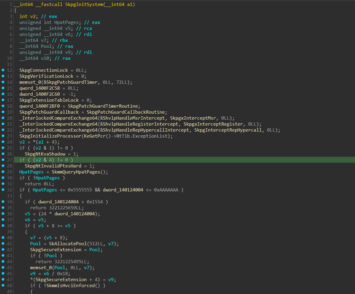
In line 20 and 21, we can see 2 atomic operations on these global pointers:

The _InterlockedCompareExchange64() is an atomic function that in this case checks if the values of ShvlpHandleMsrIntercept() and ShvlpHandleRegisterIntercept() are 0, if so it fills them with the base address of SkpgxInterceptMsr() and SkpgxInterceptRegister() respectively. These 2 functions are the “Secure Kernel Patch Guard” handler for these intercepts. For example, let’s view the SkpgxInterceptMsr():
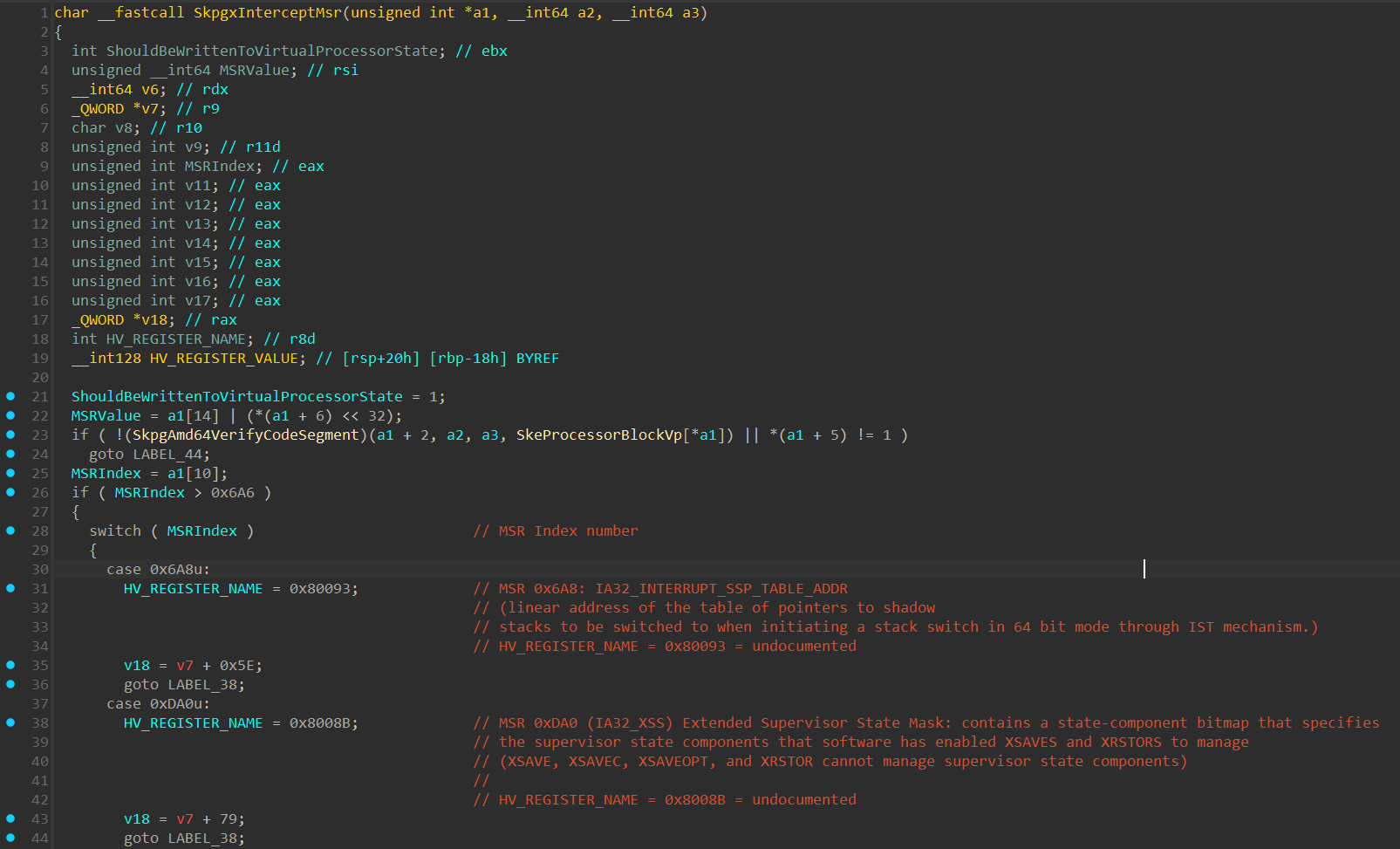
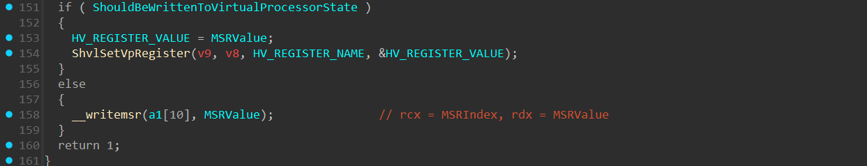
The function obtains the MSR index that’s being written, and the value intended to be written in it, and also create an int variable that’s used to determine if the MSR needs to be written through ShvlSetVpRegister() into the Virtual Processor State, I called this variable ShouldBeWrittenToVirtualProcessorState. After getting these values, a switch() statement is executed to determine the MSR index value and appropriately act on it.
The following MSRs will be written to the Virtual Processor State through the ShvlSetVpRegister() function:
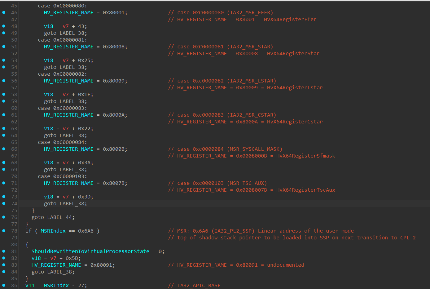
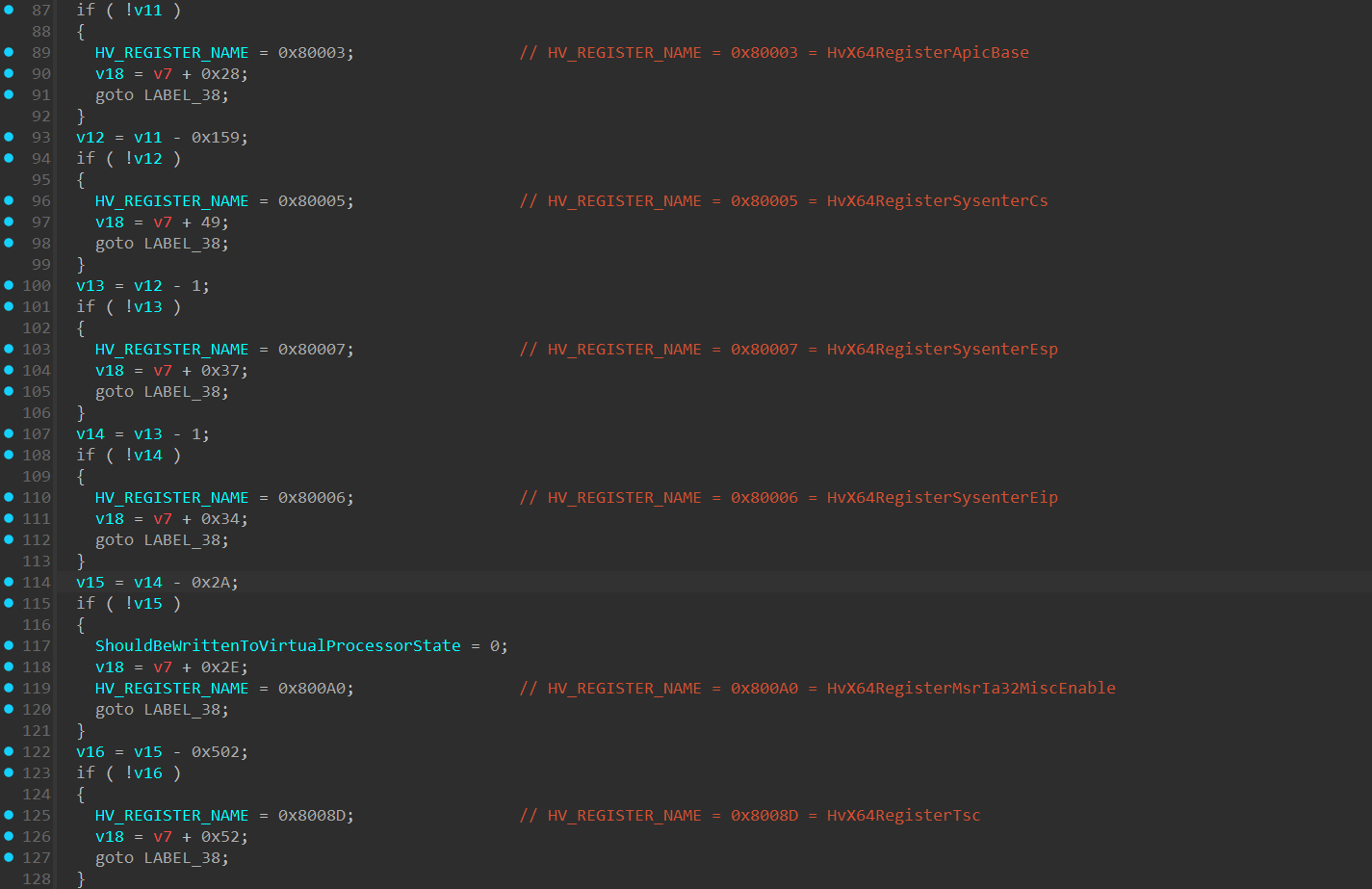
IA32_INTERRUPT_SSP_TABLE_ADDR(0x6a8) - holds the base address to the Interrupt Shadow Stack Pointer (SSP) table used in x64 architecture withIntel CET(Control-Flow Enforcement Technology).Intel CEThelps prevent stack-based control-flow attacks by maintaining a shadow stack, which is a hardware level stack that can’t be modified, and holds a copy of the return address of the original stack. In each “return” instruction, the return address in the “Shadow Stack” is compared to the return value in the original stack. Each interrupt vector has an entry in this table, which specifies the SSP value to load upon an interrupt.IA32_XSS(0xDA0) - Extended Supervisor State Mask: contains a state-component bitmap that specifies the supervisor state components that software has enabledXSAVESandXRSTORSto manage (XSAVE,XSAVEC,XSAVEOPT, andXRSTORcannot manage supervisor state components). These instructions are part of the Extended States Save/Restore mechanism in x64 architecture and are responsible to manage saving and restoring processor state.IA32_MSR_EFER(0xC0000080) - The “Extended Feature Enable Register” configures essential x64 features for the processor, such as:SYSCALL/SYSRETinstructions, Long Mode, No-Execute (NX) bit in page tables for memory protection.IA32_MSR_STAR(0xC0000081) - Defines the kernel and user-mode CS selectors for transitions during system calls.IA32_MSR_LSTAR(0xc0000082) - Holds the 64-bit base address of the syscall handler.IA32_MSR_CSTAR(0xc0000083) - Holds the 64-bit base address of the syscall handler for 32-bit processes running in 64-bit mode (Compatibility Mode).IA32_MSR_SYSCALL_MASK(0xc0000084) - Defines a mask for the RFLAGS register during SYSCALL transitions in x64.IA32_MSR_TSC_AUX(0xc0000103) - Provides additional context, such as the CPU or NUMA node ID, alongside the timestamp counter and used in conjunction with theRDTSCP(__rdtscp()compiler intrinsic call) instruction to store auxiliary information.IA32_APIC_BASE(0x1B) - holds the base address of theLocal APIC.IA32_SYSENTER_CS(0x174) - holds the CS (Code Segment) address that will be loaded into the CS register when executing asysenterinstruction in 32-bit.IA32_SYSENTER_ESP(0x175) - holds the ESP address that will be loaded into the “ESP” register when executing asysenterinstruction in 32-bit.IA32_SYSENTER_EIP(0x176) - holds the EIP address that will be loaded into the “EIP” register when executing asysenterinstruction in 32-bit.
The following MSRs will be written through wrmsr (__writemsr()) instruction:
IA32_MISC_ENABLE(0x1a0) - holds flag values to enable/disable specific processor features, such as:- fast-string operations
- automatic thermal control
- Turbo Mode in 64-bit mode.
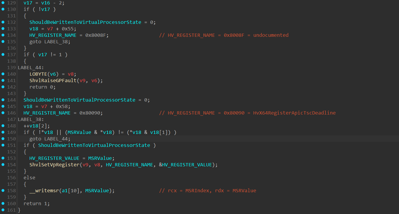
IA32_PL2_SSP(0x6A6) - holds the CPL 2 Shadow Stack Pointer.HV_REGISTER_NAMEof 0x8008F which is undocumented but my assumption it’sHvX64RegisterApicFrequencywhich holds the frequency of the Virtual APIC of the VP.HV_REGISTER_NAMEof 0x80090 which is undocumented but my assumption it’sHvX64RegisterApicTscDeadlinewhich holds the Timestamp Counter deadline of theVirtual APIC.
The actual value-writing part is performed at the end of the function and the functionality of writing the value is determined based on the ShouldBeWrittenToVirtualProcessorState boolean as we’ve just seen. If set to true, a call to ShvlSetVpRegiter() will be executed (which is a wrapper function in the Secure Kernel for the HvCallSetVpRegister() hypercall), which will write the MSR value to the Virtual Processor State of the VTL. If set to false, the value will be directly written to the Logical Processor through __writemsr() intrinsic.
1
2
3
4
5
6
7
8
9
10
11
12
13
14
15
16
17
18
19
20
21
22
23
24
25
26
27
28
29
30
31
32
33
34
35
36
37
38
39
40
41
42
43
44
45
46
47
48
49
50
51
52
53
54
55
56
57
58
59
60
61
62
63
64
65
66
67
68
69
70
71
72
73
74
75
76
77
78
79
80
81
82
83
84
85
86
87
88
89
90
91
92
typedef enum _HV_REGISTER_NAME {
    HvRegisterExplicitSuspend = 0x00000000,
    HvRegisterInterceptSuspend = 0x00000001,
    HvRegisterHypervisorVersion = 0x00000100, // 128-bit, same as CPUID 0x40000002
    HvRegisterPrivilegesAndFeaturesInfo = 0x00000200, // 128-bit, same as CPUID 0x40000003
    HvRegisterFeaturesInfo = 0x00000201, // 128-bit, same as CPUID 0x40000004
    HvRegisterImplementationLimitsInfo = 0x00000202, // 128-bit, same as CPUID 0x40000005
    HvRegisterHardwareFeaturesInfo = 0x00000203, // 128-bit, same as CPUID 0x40000006
    HvRegisterGuestCrashP0 = 0x00000210,
    HvRegisterGuestCrashP1 = 0x00000211,
    HvRegisterGuestCrashP2 = 0x00000212,
    HvRegisterGuestCrashP3 = 0x00000213,
    HvRegisterGuestCrashP4 = 0x00000214,
    HvRegisterGuestCrashCtl = 0x00000215,
    HvRegisterProcessorClockFrequency = 0x00000240,
    HvRegisterInterruptClockFrequency = 0x00000241,
    HvRegisterGuestIdle = 0x00000250,
    HvRegisterDebugDeviceOptions = 0x00000260,
    HvRegisterPendingInterruption = 0x00010002,
    HvRegisterInterruptState = 0x00010003,
    HvRegisterPendingEvent0 = 0x00010004,
    HvRegisterPendingEvent1 = 0x00010005,
    HvRegisterPendingEvent2 = 0x00010006,
    HvRegisterPendingEvent3 = 0x00010007,
    HvX64RegisterRax = 0x00020000,
    HvX64RegisterRcx = 0x00020001,
    HvX64RegisterRdx = 0x00020002,
    HvX64RegisterRbx = 0x00020003,
    HvX64RegisterRsp = 0x00020004,
    HvX64RegisterRbp = 0x00020005,
    HvX64RegisterRsi = 0x00020006,
    HvX64RegisterRdi = 0x00020007,
    HvX64RegisterR8 = 0x00020008,
    HvX64RegisterR9 = 0x00020009,
    HvX64RegisterR10 = 0x0002000A,
    HvX64RegisterR11 = 0x0002000B,
    HvX64RegisterR12 = 0x0002000C,
    HvX64RegisterR13 = 0x0002000D,
    HvX64RegisterR14 = 0x0002000E,
    HvX64RegisterR15 = 0x0002000F,
    HvX64RegisterRip = 0x00020010,
    HvX64RegisterRflags = 0x00020011,
    HvX64RegisterXmm0 = 0x00030000,
    HvX64RegisterXmm1 = 0x00030001,
    HvX64RegisterXmm2 = 0x00030002,
    HvX64RegisterXmm3 = 0x00030003,
    HvX64RegisterXmm4 = 0x00030004,
    HvX64RegisterXmm5 = 0x00030005,
    HvX64RegisterXmm6 = 0x00030006,
    HvX64RegisterXmm7 = 0x00030007,
    HvX64RegisterXmm8 = 0x00030008,
    HvX64RegisterXmm9 = 0x00030009,
    HvX64RegisterXmm10 = 0x0003000A,
    HvX64RegisterXmm11 = 0x0003000B,
    HvX64RegisterXmm12 = 0x0003000C,
    HvX64RegisterXmm13 = 0x0003000D,
    HvX64RegisterXmm14 = 0x0003000E,
    HvX64RegisterXmm15 = 0x0003000F,
    HvX64RegisterCr0 = 0x00040000,
    HvX64RegisterCr2 = 0x00040001,
    HvX64RegisterCr3 = 0x00040002,
    HvX64RegisterCr4 = 0x00040003,
    HvX64RegisterDr0 = 0x00050000,
    HvX64RegisterDr1 = 0x00050001,
    HvX64RegisterDr2 = 0x00050002,
    HvX64RegisterDr3 = 0x00050003,
    HvX64RegisterDr6 = 0x00050004,
    HvX64RegisterDr7 = 0x00050005,
    HvX64RegisterEs = 0x00060000,
    HvX64RegisterCs = 0x00060001,
    HvX64RegisterSs = 0x00060002,
    HvX64RegisterDs = 0x00060003,
    HvX64RegisterFs = 0x00060004,
    HvX64RegisterGs = 0x00060005,
    HvX64RegisterLdtr = 0x00060006,
    HvX64RegisterTr = 0x00060007,
    HvX64RegisterIdtr = 0x00070000,
    HvX64RegisterGdtr = 0x00070001,
    HvX64RegisterTsc = 0x00080000,
    HvX64RegisterEfer = 0x00080001,
    HvX64RegisterKernelGsBase = 0x00080002,
    HvX64RegisterApicBase = 0x00080003,
    HvX64RegisterPat = 0x00080004,
    HvX64RegisterSysenterCs = 0x00080005,
    HvX64RegisterSysenterRip = 0x00080006,
    HvX64RegisterSysenterRsp = 0x00080007,
    HvX64RegisterStar = 0x00080008,
    HvX64RegisterLstar = 0x00080009,
    HvX64RegisterCstar = 0x0008000A,
    HvX64RegisterSfmask = 0x0008000B,
    HvX64RegisterInitialApicId = 0x0008000C
} HV_REGISTER_NAME;
The 4th argument in the ShvlSetVpRegister() function is an union of HV_REGISTER_VALUE:
1
2
3
4
5
6
7
8
9
10
11
12
13
14
15
16
17
18
19
typedef union
{
    UINT128 Reg128;
    UINT64 Reg64;
    UINT32 Reg32;
    UINT16 Reg16;
    UINT8 Reg8;
    HV_X64_FP_REGISTER Fp;
    HV_X64_FP_CONTROL_STATUS_REGISTER FpControlStatus;
    HV_X64_XMM_CONTROL_STATUS_REGISTER XmmControlStatus;
    HV_X64_SEGMENT_REGISTER Segment;
    HV_X64_TABLE_REGISTER Table;
    HV_EXPLICIT_SUSPEND_REGISTER ExplicitSuspend;
    HV_INTERCEPT_SUSPEND_REGISTER InterceptSuspend;
    HV_X64_INTERRUPT_STATE_REGISTER InterruptState;
    HV_X64_PENDING_INTERRUPTION_REGISTER PendingInterruption;
    HV_X64_MSR_NPIEP_CONFIG_CONTENTS NpiepConfig;
    HV_X64_PENDING_EXCEPTION_EVENT PendingExceptionEvent;
} HV_REGISTER_VALUE, *PHV_REGISTER_VALUE;